


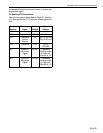

SECTION 6: ULTRAVAC™ BMS LINK CONTROLLER
39 of 62
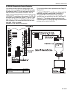
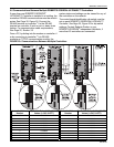
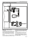
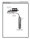
FIGURE 24: ULTRAVAC™ BMS Link Controller Schematic
6.2 ULTRAVAC™ BMS Link Controller
Requirements
The purpose of the ULTRAVAC™ BMS Link Control-
ler is to integrate with a third party building control
system. This building control system is provided by
others and must be capable of communicating via
one of the ULTRAVAC™ BMS Link communication
protocols.
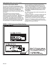
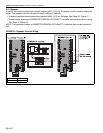
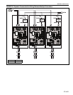
For interface capability, one ULTRAVAC™ BMS Link
Controller is needed for each ULTRAVAC™ network
of controllers. The ULTRAVAC™ BMS Link Controller
is connected via communication wiring on the RS-
485 communication bus to the ULTRAVAC™ central
controller.
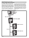
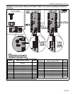
The ULTRAVAC™ BMS Link Controller requires a
115 V, 20 A dedicated power circuit. The control
board identification dip switch must be set on each
ULTRAVAC™ controller. See Page 41, Figure 25.
This enables ULTRAVAC™ Controls to communicate
with a variety of controls.