


ROBERTS GORDON
®
ULTRAVAC™ CONTROLLER INSTALLATION MANUAL
40 of 62
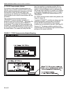
6.3 Technical Data
• Power Supply: 120 VAC.
• Frequency: 50/ 60 Hz.
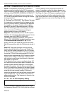
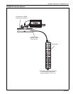
• Network Cable: Standard Ethernet Cables.
• Communication Ports: RS-485 Communication Bus
• Memory: Memory Card, SD 1GB.
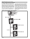
6.4 ULTRAVAC™ BMS Link Controller
Programming
Each ULTRAVAC™ BMS Link Controller is custom
programmed before it is shipped. The custom pro-
gram allows the controller to interface with the proper
total number of ULTRAVAC™ Controls installed at
the jobsite. The total number of ULTRAVAC™ Con-
trols (including the central controller and all satellite
controllers, but not including the ULTRAVAC™ BMS
Link Controller) and the job name and location are
submitted to Roberts-Gordon upon placing the order
for the ULTRAVAC™ BMS Link Controller.
Each ULTRAVAC™ BMS Link Controller is supplied
with a printed report listing all of the available points.
The information in the report must be communicated
to the controls manager for use in configuring the
third party building controls software. This documen-
tation is intended for the contractor to leave with the
controls manager or end user upon commissioning
of the ULTRAVAC™ system. Refer to the
ULTRAVAC™ BMS Link Controller User Manual
included on our ULTRAVAC™ Software CD for onsite
programming instructions.