


TABLE OF FIGURES
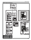
Figure 1: ULTRAVAC™ Controller Label Placement.................4
Figure 2: ULTRAVAC™ BMS Link Controller Label Placement 5
Figure 3: VFD Label Placement................................................6
Figure 4: Repeater Label Placement ........................................7
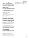
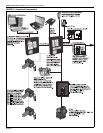
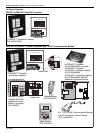
Figure 5: Connected Components ............................................8
Figure 6: Example Site Layout ................................................ 15
Figure 7: ROBERTS GORDON
®
ULTRAVAC™ Controller
Specifications ..........................................................18
Figure 8: Variable Frequency Drive Components
(Factory pre-wiring shown) ......................................20
Figure 9: Controller Mounting..................................................21
Figure 10: Variable Frequency Drive Mounting........................23
Figure 11: Indoor Sensor Mounting.........................................24
Figure 12: Outdoor Sensor Placement....................................24
Figure 13: ROBERTS GORDON
®
ULTRAVAC™ Central
Controller External Wiring ......................................26
Figure 14: ROBERTS GORDON
®
ULTRAVAC™ Satellite
Controller External Wiring ......................................28
Figure 15: Modem Location ....................................................30
Figure 16: RS-485 PC Connection..........................................31
Figure 17: TCP/IP Communication Module Mounting.............32
Figure 18: TCP/IP Communication Module Wiring..................33
Figure 19: 9 Pin Adapter for PC ..............................................34
Figure 20: Communications Between Multiple Controllers .....35
Figure 21: Repeater External Wiring ......................................36
Figure 22: Repeater Communication Wiring Between Multiple
Controllers..............................................................37
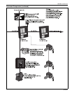
Figure 23: Standard ULTRAVAC™ BMS Link Architecture .....38
Figure 24: ULTRAVAC™ BMS Link Controller Schematic ......39
Figure 25: Communication Between ULTRAVAC™ BMS Link
Controller and Multiple ULTRAVAC™ Controllers ..41
Figure 26: End Vent Vacuum ..................................................45
Figure 27: Possible Damper Couplings’ Locations..................46
Figure 28: Troubleshooting Flow Chart ...................................49
Figure 29: Troubleshooting Flow Chart - Repeater .................53
Figure 30: Trou
bleshooting Flow Chart - BACnet
®
..................54
Figure 31: ROBERTS GORDON
®
ULTRAVAC™ Controller
Components Diagram............................................56
Figure 32: Variable Frequency Drive Components Diagram ...57
Figure 33: ULTRAVAC™ BMS Link Controller Components
Diagram .................................................................58
Figure 34: Repeater Components Diagram ............................59