


ROBERTS GORDON
®
ULTRAVAC™ CONTROLLER INSTALLATION MANUAL
30 of 62
SECTION 5: COMMUNICATIONS
One ROBERTS GORDON
®
ULTRAVAC™ Controller
per building (called the "central controller") must
have equipment for remote communications to a PC.
This equipment consists of either a modem chip, an
RS-485 converter, or a TCP/IP communications
module.
For remote on-site and off-site control and system
status viewing, the central controller (controller
#
1) is
fitted with a modem chip. See Page 30, Section 5.1.
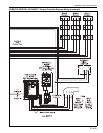
If only remote on-site control and system status
viewing is required, two controller communications
interface devices are available: an RS-485 converter
or a TCP/IP communication module.
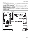
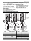
An RS-485 converter is installed at a single PC, this
PC can interface with any controller on the network
of ULTRAVAC™ controllers. The RS-485 converter at
the PC is wired directly to controller #1 using
shielded twisted pair communication wiring.
See Page 31, Figure 16.
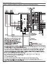
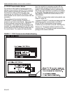
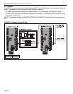
To interface with ULTRAVAC™ controllers through a
Local Area Network (LAN), a TCP/IP Communication
module is installed at controller #1. Controller #1 is
wired to the LAN by an Ethernet cable. See Page 32,
Section 5.3. Any computer on the LAN that has
ULTRAVAC™ software installed can communicate
with the controllers. Appropriate precautions must be
taken to protect the Ethernet wiring from any possible
electrical interference (noise) caused by surrounding
machinery or equipment.
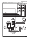
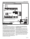
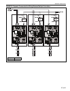
If multiple ULTRAVAC™ controllers are being used,
the additional controllers communicate to controller
#1 through communication wiring arranged in-series
from one controller to the next. See Page 35, Section
5.5.
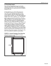
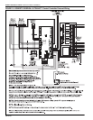
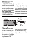
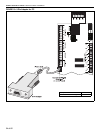
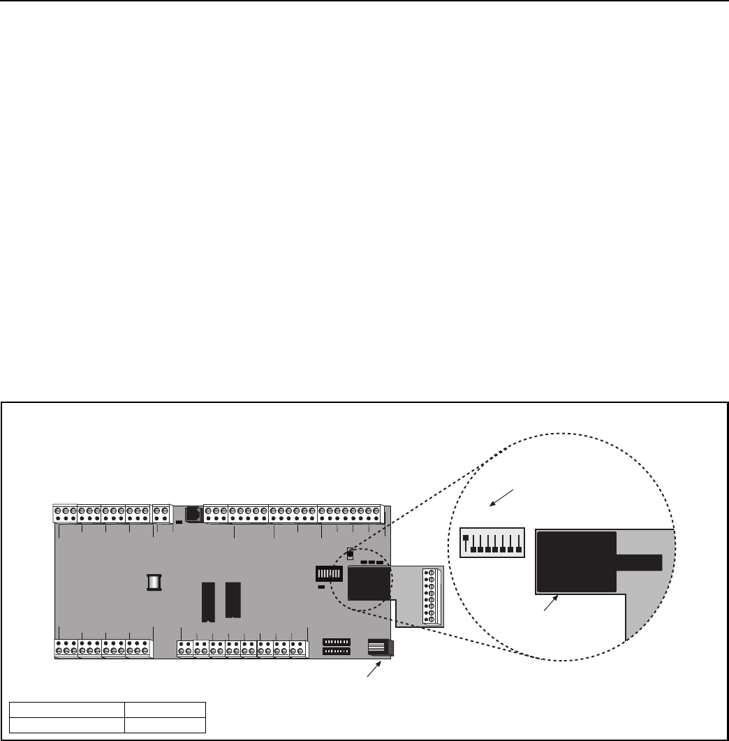
FIGURE 15: Modem Location
5.1
Dedicated Phone Line for Central Controller
Modem
The Central Controller is fitted with a modem chip. To
use the modem, the controller must have a phone
line for modem communications. Install a phone line
near the location of the Central Controller. The phone
cable is plugged into the phone connection in the
corner of the control board. See Page 30, Figure 15.
If the modem option is not used for everyday commu-
nication to the controller(s), it can still be plugged into
a phone line for troubleshooting or programming
assistance. Contact your local ROBERTS GOR-
DON
®
independent distributor for details.
If multiple ULTRAVAC™ controllers are being used, the
additional controllers communicate to controller #1
through RS-485 communication wiring arranged
in-series from one controller to the next.
See Page 35,
Section 5.5
.
This allows multiple controllers to be
controlled from a PC through a single communication
package at the central controller.
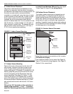
Control Board of the
Central Controller
Phone Cable Connection
+-
1
+-
2
+-
4
+-
3
+-
5
+-
6
+-
7
+-
8
+- +-
REF
24VAC
L2
NONC C
NONC CNONC CNONC CNONC C
NONC CNONC CNONC C
RS485 COMM
REF
+-
1
+-
2
+-
3
+-
4
METER INPUTS
UNIVERSAL INPUTS
INOUT
ADDRESS
RESET
10VDC
499 OHM
OFF
ON
OUT
IN
GINOUT G G G
+5
+32
AUX POWER
RS232 DIRECT
RI
CDOH
CPU
L1
PWR
Dip Switch
#
1
Set to ON
Installed
Modem Chip
Modem
Chip
1 2 3 4 5 6 7 8
Description Part Number
Modem Chip 10080142