


NEVER use open flame to test for gas leaks, as bodily injury or
property damage could result.
PRESSURE TESTING THE GAS SUPPLY SYSTEM — The water
heater and its manual gas shut-off valve MUST be disconnect-
ed from the gas supply piping system during any high pressure
testing of that system at pressures in excess of 1/2 psi
(14” w.c. / 3.5 kPa).
The water heater MUST be isolated from the gas piping system
by closing the manual gas shut-off valve during any pressure test-
ing of the gas supply piping at pressures equal to or less than
1/2 psi (14” w.c. / 3.5 kPa).
5. VENTING —
The water heater must be vented to the outdoors as described
in these instructions. DO NOT connect this water heater to an
existing Vent or Chimney it must be vented separately from all
other appliances.
Failure to properly vent the water heater to the outdoors as outlined
above and in the following section can result in unsafe operation of
the water heater causing bodily injury, explosion, fire or death.
To avoid the risk of fire, explosion or asphyxiation from carbon
monoxide, NEVER operate this water heater unless it is properly
vented and has an adequate air supply for proper operation. The
vent pipe must overlap a minimum of ½" on each connection. It is
important that the vent pipe engages fully into any pipe fitting and
be kept in that position until the adhesive has fully cured. DO NOT
drill or punch holes in the plastic pipe or fittings.
NOTICE: This unit can be vented using only the following
recommended pipe material. Use only 3- or 4-inch diameter pipe.
PVC (Schedule 40, ASTM D-1785)
CPVC (Schedule 40, ASTM F-441)
ABS (Schedule 40, ASTM D-2661)
The fittings, other than the VENT TERMINAL, should be equiva-
lent to the following:
PVC (Schedule 40 DWV, ASTM D-2665)
CPVC (Schedule 40 DWV, ASTM F-438)
ABS (Schedule 40 DWV, ASTM D-2661)
The unit may be vented horizontally through a wall or vertically through
the roof. Pipe runs must be adequately supported along both vertical
and horizontal runs. Maximum unsupported span is recommended to
be no more than 4 feet. It is imperative that the first hanger be located
on the horizontal run immediately adjacent to the first 90-degree elbow
from the vertical rise or at the blower outlet in the case of a horizontal
blower position. Support method used should isolate the vent pipe from
floor joists or other structural members to help prevent the transmission
of noise and vibration. Do not support, pin or otherwise secure the vent-
ing system in a way that restricts the normal thermal expansion and
contraction of the chosen venting material.
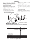
If the water heater is being installed as a replacement for an existing
power vented water heater, a thorough inspection of the existing venting
system must be performed prior to any installation work. Verify that the
correct materials, as detailed above have been used, and that the mini-
mum or maximum vent length and terminal locations as detailed in this
manual have been met. Carefully inspect the entire venting system for
any signs of cracks or fractures, particularly at the joints between elbows
or other fittings and the straight runs of vent pipe. Check the system for
signs of sagging or other stresses in the joints as a result of misalignment
of any components in the system. If any of these conditions are found,
they must be corrected in accordance with the venting instructions in this
manual before completing the installation and putting the water heater
into service.
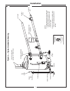
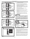
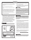
VENT PIPE CONNECTION —
The blower assembly is preinstalled at the factory, so all that is required
for connecting the vent system is attaching the vent pipe to the blower
and the PVC Tee. Before starting the vent installation, careful planning
should be given to the routing and termination of the vent pipe. The length
of the vent pipe (inlet and outlet) should be kept to a minimum. Also, see
page 10 & 12 for vent terminal placement. The GP100-150 & GP100-200
model can be vented using either 3 inch or 4 inch Schedule 40 PVC pipe
and fittings.
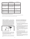
To use 3 inch PVC, you can connect directly to the blower outlet (rubber
coupling provided for outlet connection) and PVC Tee. Make sure that
clamps on rubber coupling are tight, after the pipe is installed. The inlet
vent pipe should be cemented into the PVC Tee.
If 4 inch PVC pipe is going to be used, then it will be necessary to have
a short piece ( at least 3 inches long ) of 3 inch PVC pipe to join into the
coupling and tee. Then a 4 X 3 reducer would need to be joined to the
short piece of pipe, so that the 4 inch pipe could be used. The 4 inch pipe
will then need to be stepped back down, using a 4 X 3 reducer, to 3 inch
PVC. To install the vent terminals, a short length of 3 inch (maximum of
16 inches long) pipe will need to be used. (Refer to Figure 9b on page
10.)
The GP100-250 model can only be vented using 4 inch Schedule 40 PVC
pipe and fittings. The 4 inch pipe can be connected directly to the blower
coupling and 4 inch tee.
8
Installation
WARNING
!
WARNING
!
WARNING
!
WARNING
!
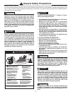
Outlet
Vent Connection
Inlet
Vent Connection
Figure 5.
—
Vent Pipe Connection Locations