


11
Installation
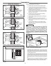
3. Maximum twenty-four (24) inches above roof level without
additional support for vent pipe.
4. Four (4) feet from any gable, dormer or other roof structure with
building interior access (i.e., vent, window, etc.).
5. Ten (10) feet from any forced air inlet to the building. Any
fresh or make-up air inlet such as a dryer or furnace area is
considered to be a forced air inlet.
6. The inlet is a minimum of six (6) inches vertically above the outlet.
7. Terminals are a minimum of seven (7) inches horizontally apart with
a maximum of twenty-four (24) inches.
VENT INSTALLATION – Before proceeding, make certain you
understand the procedure and cautions covered in the section
“Joining Pipes and Fittings.”
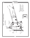
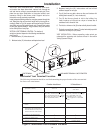
VERTICAL VENT INSTALLATION – Once the vent termi-
nal location has been determined, make a hole through the
roof and interior ceiling to accommodate the vent pipe. Com-
plete the vent pipe installation to the water heater’s vent
connector fitting on the blower outlet. Support vertical or
horizontal runs as previously mentioned.
Install adequate flashing where the vent pipe passes through the
roof. Determine the vent terminal height and cut vent pipe ac-
cordingly. Refer to Fig. 8 for proper vent terminal height. Connect
vent elbow onto vertical pipe through roof. Connect short piece
of vent pipe (approximately 3
"
long) to elbow, then join terminal
to the short piece of vent pipe.
VERTICAL VENT TERMINAL LOCATION – The location of
vertical vent terminal depends on the following considerations
(see Figure 8):
1. Minimum twelve (12) inches above roof.
2. Minimum twelve (12) inches above anticipated snow level.
D
V
V
E
F
IX
ED
C
L
OS
ED
O
P
E
R
A
BL
E
O
P
E
R
A
B
L
E
FIXE
D
CL
O
S
ED
v
v
B
L
F
C
B
v
v
v
X
B
B
B
A
J
C
I
H
X
v
M
K
v
G
A
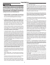
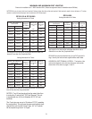
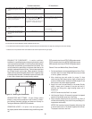
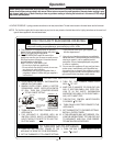
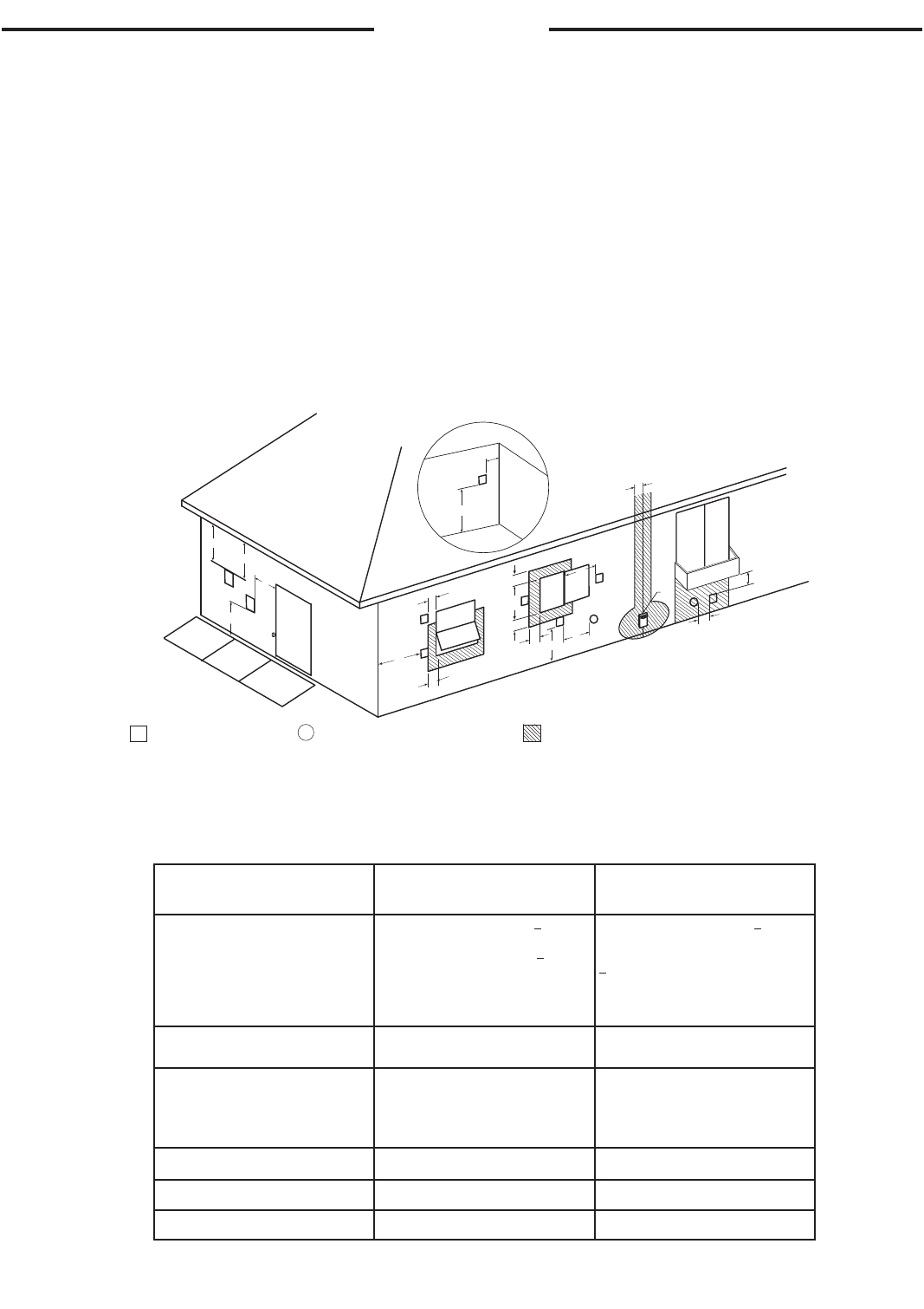
The following information should be used for determining the proper location of the vent terminal
for direct vent water heaters.
V
VENT TERMINAL
X
AIR SUPPLY INLET
AREA WHERE TERMINAL IS NOT PERMITTED
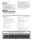
Horizontal Vent Terminal Location
Canadian Installations
1
US Installations
2
A= Clearance above grade, veranda,
porch, deck or balcony.
12 inches (30 cm) above anticipated
snow level.
12 inches (30 cm) above anticipated
snow level.
B= Clearance to window or door that may
be opened.
6 inches (15 cm) for appliances < 10,000
Btuh (3 kW), 12 inches (30 cm) for appli-
ances > 10,000 Btuh (3kW) and < 100,000
Btuh (30kW), 36 inches (91 cm) for appli-
ances > 100,000 Btuh (30kW).
6 inches (15 cm) for appliances < 10,000
Btuh (3 kW), 9 inches (23 cm) for appli-
ances > 10,000 Btuh (3 kW) and
< 50,000 Btuh (15 kW), 12 inches
(30 cm) for appliances > 50,000 Btuh
(15 kW).
C= Clearance to permanently closed
window.
* *
D= Vertical Clearance to ventilated soffit
located above the terminal within a
horizontal distance of 2 feet (61 cm)
from the center line of the terminal.
3 feet (91 cm) 3 feet (91 cm)
E= Clearance to unventilated soffit. * *
F= Clearance to outside corner. * *
G= Clearance to inside corner. 18 inches (46 cm) 18 inches (46 cm)
Figure 9 - Horizontal Vent Terminal Location