17
Properly maintained, this water heater will provide years of dependable,
trouble free service. It is strongly suggested that a regular routine main-
tenance program be established and followed by the owner. It is further
recommended that a periodic inspection of the blower, thermostat, burner,
relief valve, internal flueway, draft hood / damper assembly and venting
system should be made by service technicians qualified in gas appliance
repair.
1. ROUTINE PREVENTIVE MAINTENANCE
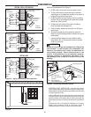
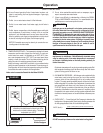
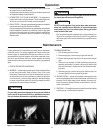
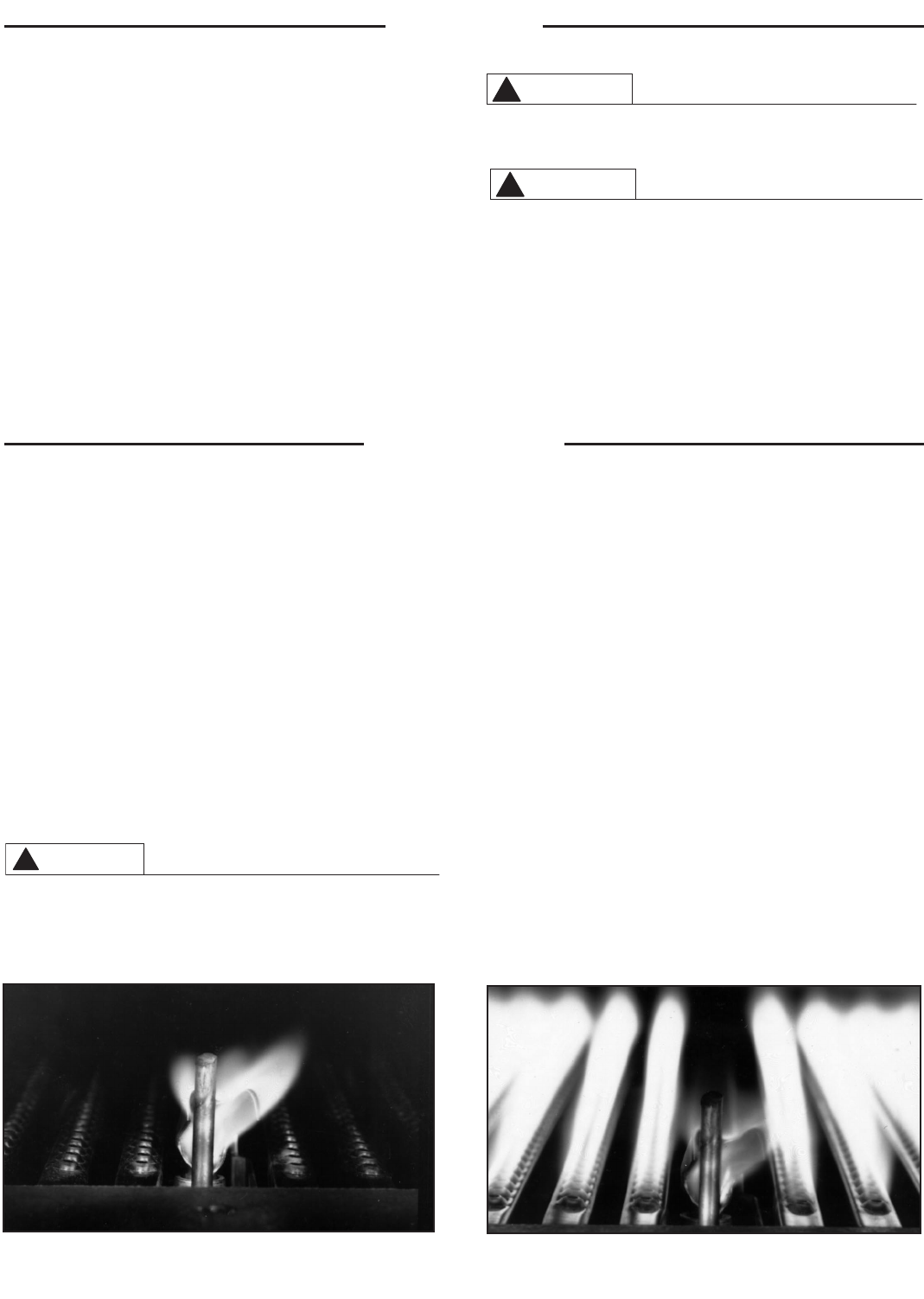
A. BURNERS — Visually inspect the main burner flame and the pilot flame
at least every three months. Refer to Figures 12 and 13 for normal
flame pattern. Fallen scale can usually be dislodged from the tops of
the burners with a thin rod, then vacuumed or brushed from the bottom
of the burner box. If a more thorough cleaning is deemed necessary
to restore a normal flame pattern, the burner tray assembly should be
removed and the burners cleaned individually.
For your safety, removal and cleaning of burner tray and individual
burners should be performed ONLY by a qualified service techni
-
cian, as it involves disconnection of gas piping and leak testing.
TO REMOVE BURNER TRAY:
1. Turn off manual gas shut-off valve.
2. Disconnect gas pipe union and wiring to gas valve and pilot.
3. Remove retaining screws from plate on the same side as the gas
valve.
4. Slide burner tray assembly out. When reinstalling the burner tray
assembly, make certain it is pushed in all the way so that the plate
lines up with the holes in the plenum side. Then reinstall the retain-
ing screws.
5. Reconnect gas pipe union and wiring to gas valve and pilot, turn
on manual gas shut-off valve and test for gas leak.
B. VENTING SYSTEM — Inspect venting system at least yearly to make
certain the passageways are free and unobstructed, and that the vent
connector from the water heater’s blower assembly is properly posi-
tioned and securely attached. Remove any obstructions in vent con-
nector or vent terminal.
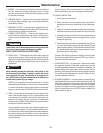
C. CONTROLS — The manifold pressure and controls should be checked
at least yearly by a qualified service technician.
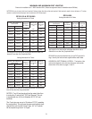
To insure accuracy for rating, clock enough cubic feet of gas so that
the clocked time is at least 60 seconds.
Small adjustments can be made by varying the manifold pressure from
the designated settings mentioned above.
5. INTERMITTENT PILOT FLAME ADJUSTMENT — No adjustment is
required with normal inlet gas pressures. The pilot flame adjustment
valve is pre-set, and does not normally require re-adjustment.
6. HIGH ALTITUDE — Ratings of gas appliances are based on installation
and operation at sea level of elevations of 2000 feet.
Factory prepared high altitude models are available and are specifically
rated for installation at elevation up to 8000 feet. Refer to rating plate
on the front of the water heater for number and altitude specifications.
Also refer to the supplement sheet for information on venting high
altitude models.
7. EMERGENCY SHUTDOWN —
Should overheating occur or the gas supply fail to shut off, turn off
the manual gas control valve to the appliance.
DO NOT use this appliance if any part has been under water. Imme
-
diately call a qualified service technician to inspect the appliance
and to replace any part of the control system and any gas control
which has been under water.
If the water heater has been subjected to fire or physical damage, turn
off gas at the manual gas control (shut-off) valve. Do not operate the
water heater again until it has been checked out by a qualified service
technician.
Operation
Maintenance
WARNING
!
Figure 12. — Pilot Flame Pattern
Figure 13. — Pilot & Main Burner Flame Pattern
CAUTION
!
WARNING
!


