


19
®
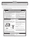
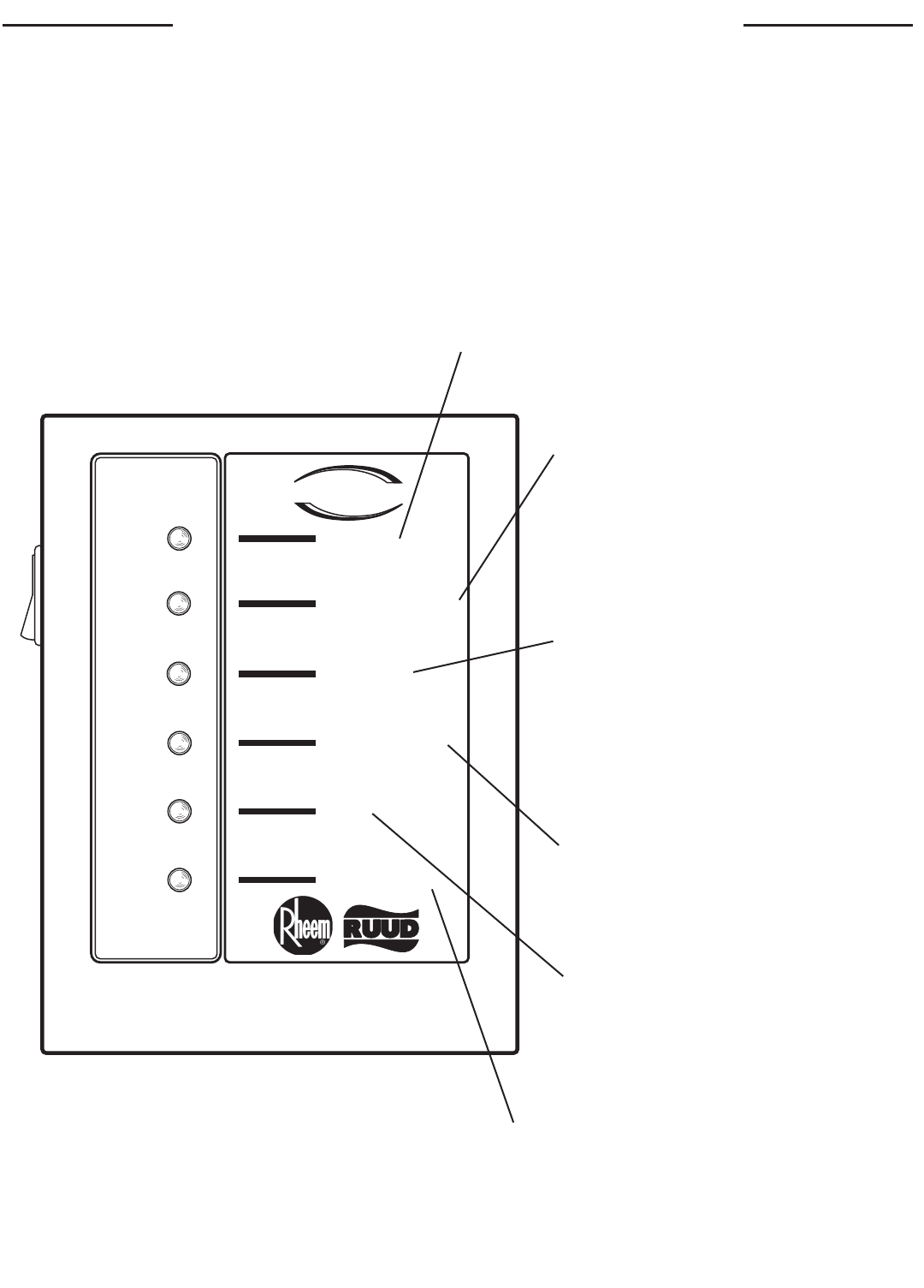
SYSTEM SENTINEL
POWER
THERMOSTAT
IGNITION
PILOT VALVE
MAIN VALV E
ECO
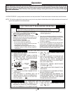
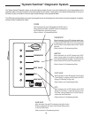
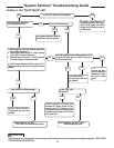
“System Sentinel” Diagnostic System
The “System Sentinel” Diagnostic system on this water heater provides the user or service technician with a visual representation of the
operational status of the various sections of the water heater’s control system. A quick glance at the System Sentinel panel on the front of
the heater will give an indication of where to begin trouble shooting of a non operational heater.
The LED’s (light emitting diodes) on the panel are arranged from top to bottom based on their function in the normal sequence of operation,
and their function is explained as follows:
POWER
When illuminated, this green LED indicates that 120VAC power is
being supplied to the heater, the ON/OFF switch is functioning and
the 24V transformer is functioning properly.
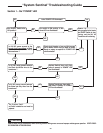
(Refer to Section 1 of Troubleshooting Guide)
THERMOSTAT
When illuminated, this red LED indicates that the ther-
mostat is functioning(calling for heat) and 24VAC power
is being supplied to the relay (to turn on the blower) and
the N/C terminal of the pressure switch with N/C and N/O
terminals.
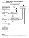
(Refer to Section 2 of Troubleshooting Guide)
IGNITION
When illuminated, this red LED indicates that 24 VAC
power is being supplied to the Ignition Control Module,
and the ignition sequence has begun. The N/O side of the
pressure switch with N/C and N/O terminals closes
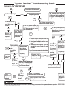
(Refer to Section 3 of Troubleshooting Guide)
PILOT VALVE
When illuminated, this red LED indicates that the Ignition
Control Module is supplying 24 VAC power to the ECO
(Energy Cut Off device), or High Limit.
(Refer to Section 4 of Troubleshooting Guide)
ECO
When illuminated, this red LED indicates that the ECO
(Energy Cut Off device), or High Limit is closed, and 24
VAC power is being supplied to the PV (Pilot Valve) ter-
minal on the Gas Control Valve.
(Refer to Section 5 of Troubleshooting Guide)
MAIN VALVE
When illuminated, this red LED indicates that the Ignition Control
Module is supplying 24 VAC power to the MV (Main Valve) terminal
on the Gas Control Valve.
(Refer to Section 6 of Troubleshooting Guide)