


Page 47
REMINGTON QFP40 Direct Vent FIREPLACE
250-4721 JUNE 2001
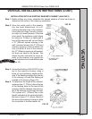
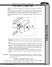
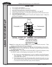
ELECTRICAL CONNECTION
Make sure the household breaker is shut off prior to working on any electrical
lines.
This appliance, when installed, must be electrically grounded in acordance
with local codes or, in the absence of local codes, with the National Electrical
Code, ANSI/NFPA 70, or the Canadian Electrical Code, CSA C22.1.
The electrical line must be at least 14 gauge and supply 120 Volts at 60 Hz (2
Amps)
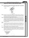
Remove the junction box cover at the right rear corner of the fireplace near
the base.
Feed the electrical line through the strain relief (use insulated Romex type
wire).
Remove the wires from the junction box. Expose approximately 1/2” of metal
wire from each line of the electrical line. Use wire nuts to secure the wires
together. Connect copper ground wire to grounding screw as shown in fig-
ure above, connect the white wire to the common wire (usually white), and
the black wire to the hot wire (usually black).
Push the wire connections into the junction box. Replace the cover plate.
Tighten the strain relief onto the outer insulation of the electrical line to se-
cure.
CAUTION: Label all wires prior to disconnection when servicing controls. Wiring er-
rors can cause improper and dangerous operation. Verify proper opera-
tion after servicing.
OPTIONAL THERMOSTAT INSTALLATION
A remote control or wall switch may be wired to the TH and TPTH thermostat terminals.
See Parts and Accessories on page 66 to order through your dealer.
ELECTRICAL
COPPER
WIRE
WHITE
BLACK