


REMINGTON QFP40 Direct Vent FIREPLACE
Page 40
250-4721 JUNE 2001
VERTICAL INSTALLATION INSTRUCTIONS (CONT.)
USING GS SERIES PIPE (CONT.)
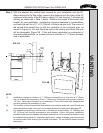
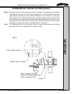
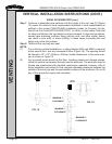
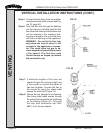
Step 7. Continue to assemble pipe sections until the height of the vent cap (H) (Figure
15) meets the minimum code requirements described in code requirements as
outlined in the current CAN/CGA-Bl49 Installation Codes (in Canada), the Na-
tional Fuel Gas Code NFPA 54/ANSI Z223.1 (in USA), or local codes. Note that
for steep roof pitches, the vent height must be increased. In high wind conditions,
nearby trees adjoining rooflines, steep pitched roofs, and other similar factors
can result in poor draft, or down drafting. In these cases increasing the vent
height may solve this problem.
Step 8. Twist-lock the vent cap and seal.
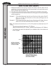
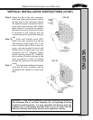
NOTE:
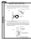
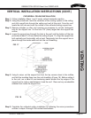
(1) For multi-story vertical installations, a ceiling firestop (SDV part #963) is required
at the second floor, and any subsequent floors (Figure 16). The opening should
be framed to 10" x 10" (254mm x 254mm) inside dimensions, in the same man-
ner as shown in Figure 13.
(2) Any occupied areas above the first floor, including closets and storage spaces,
which the vertical vent passed through must be enclosed. The enclosure may be
framed and sheetrocked with standard construction materials; however, refer to
these installation instructions for the minimum allowable clearance between the
outside of the vent pipe and the combustible surfaces of the enclosure. Do not fill
any of the required air space with insulation.
VENTING
FIG. 15
FIG. 16
MINIMUM 1"
CLEARANCE
MINIMUM 1"
CLEARANCE
MINIMUM 1"
CLEARANCE