


Page 35
REMINGTON QFP40 Direct Vent FIREPLACE
250-4721 JUNE 2001
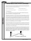
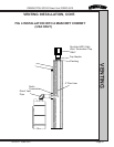
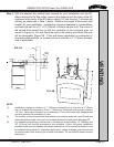
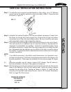
Step 3. With the adapter, any vertical pipe required for your installation, and the 90°
elbow attached to the flue outlet, measure the distance from the base of the ZC
appliance to the center of the 90° elbow, adding 1/4" rise for every 1' of horizontal
venting, as referenced in Note 1, below. Measure this height at the correct wall
location for your installation, maintaining minimum clearance to combustibles,
and mark the wall for a 10" x 10" (254mm x 254mm) square hole. The center of
the square hole should line up with the centerline of the horizontal pipe, as
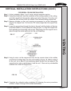
shown in Figure 6A. Cut and frame the hole in the exterior wall where the vent
will be terminated, Figure 6B. If the wall being penetrated is constructed of
noncombustible material, i.e. masonry block or concrete, a 7" (178mm) diameter
hole is acceptable.
NOTE:
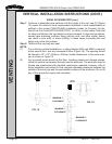
(1) Installation requires a minimum of 1' (305mm) horizontal run of vent with a ¼" (6mm)
rise run towards the termination. Each 1' (305mm) of horizontal venting must include a
1/4" rise. Never allow the vent to run downward. This could cause high temperatures
and may present the possibility of a fire.
(2) The location of the horizontal vent termination on an exterior wall must meet all local and
national building codes, and must not be easily blocked or obstructed, see page 33.
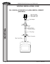
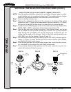
(3) For installations requiring a vertical rise on the exterior of the building, 14" (356mm) and
36" (914mm) tall snorkel terminations are available. Follow the same installation
procedures as used for standard horizontal terminations. If the snorkel termination must
be installed below grade (i.e. basement application), proper drainage must be provided
to prevent water from entering the snorkel termination. Do not backfill around snorkel
termination.
VENTING
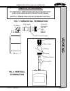
FIG. 6A
10"
10"
49"
Center
Line
Center
of Hole
Center Line
Wall
10' x 10'
Opening
FIG. 6B