


Regency
®
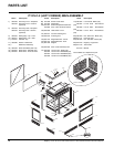
P121-2/P121LC-2/P121RC-2/P131-2 Zero Clearance Direct Vent Gas Fireplace
38
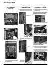
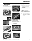
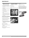
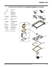
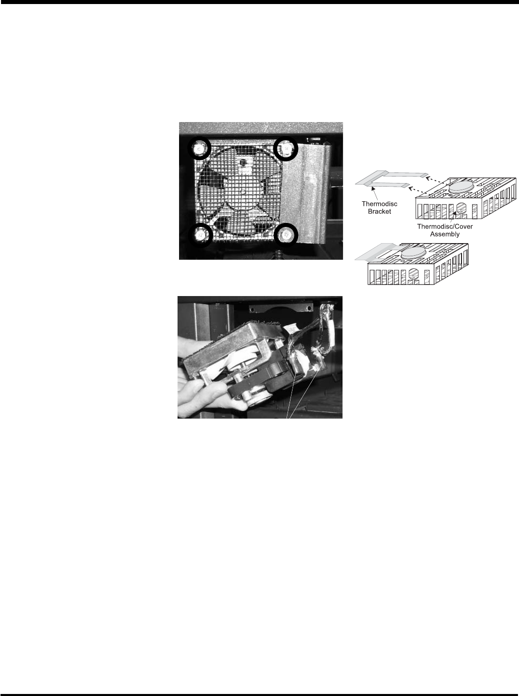
FAN REPLACEMENT
1) Shut off power.
2) Remove top louvers.
3) Unplug power wires.
4) Remove 4 screws securing fan to mounting
bracket.
MAINTENANCE
5) Remove 2 connector wires.
6) Replace fan.
7) Repeat for opposite side/corner.
8) Reverse steps 1 - 5 for installation.
9) To remove the thermodisc, located at the back
center of the unit, slide the thermodisc/cover
assembly away from the bracket clip on the
under side of the fi rebox. Reverse for installation.
Ensure that no wires will touch hot surfaces.
Connector wires
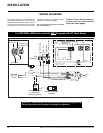
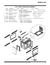
INSTALLING VALVE
1) Attach the valve to the valve bracket with
the 6 (m5x8 metric) screws provided.
2) Reconnect the "gas out" fl are fi tting with an
11/16" wrench.
3) Reconnect the "gas out" fl are nut with a
13/16" wrench.
4) Install piezo ignitor push button assembly
and reconnect wire.
5) Reconnect the quick drop out thermocouple
nut with a 9mm wrench.
6) Reconnect the pilot tube nut with a 7/16"
wrench.
7) Scrape off the old gasket from the fl oor of the
fi rebox and from the valve tray assembly.
8) Install a new gasket and reinstall the valve
tray assembly.
Note: Failure to install a new gasket may
severely affect the appliance performance.
9) Reinstall the 16 hold down screws.
10) Hook up the 2 TP and 2 TH wires to the
appropriate connections on the valve.
11) Reinstall the Burner Assembly.
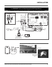
13) Hook up the gas line and check for gas
leaks with a soap and water solution or a
gas leak detector. (Do not use open fl ame
for leak testing.)
14) Fire up the unit temporarily
15) Check the manifold pressure.
16) Reinstall the logs, grate and brick panels
as needed.
17) Reinstall the glass doors.
18) Fire up the unit again and check for proper
fl ame appearance.