


Regency
®
P121-2/P121LC-2/P121RC-2/P131-2 Zero Clearance Direct Vent Gas Fireplace 21
INSTALLATION
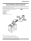
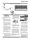
HORIZONTAL
TERMINATIONS
Install the vent system according to the
manufacturer's instructions included with
the components.
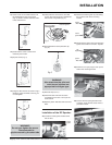
1) Set the unit in its desired location. Check
to determine if wall studs or roof rafters
are in the way when the venting system is
attached. If this is the case, you may want
to adjust the location of the unit. Rough in
the gas.
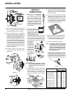
2) Direct Vent pipe and fi ttings are designed
with special twist-lock connections to
connect the venting system to the appliance
fl ue outlet. A twist-lock appliance adaptor
is an available option that must be used in
conjunction with the Simpson Dura-Vent
Direct Vent GS system.
3) Put a bead of silicone inside the outer
section of the adapter and a bead of Mill
Pac on the inner collar. Slip the adapter
over the existing inner and outer fl ue collar
and fasten to the outer collar only with the
3 supplied screws (drilling pilot holes will
make this easier). Level the fi replace and
fasten it to the framing using nails or screws
through the nailing strips.
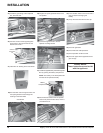
4) Assemble the desired combination of pipe
and elbows to the appliance adaptor and
twist-lock for a solid connection.
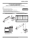
Note:
a) Twist-lock procedure: Four indentations,
located on the female ends of pipes and
fi ttings, are designed to slide straight
onto the male ends of adjacent pipes
and fi ttings, by orienting the four pipe
indentations so they match and slide
in to the four entry slots on the male
Diagram 1
Diagram 2
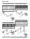
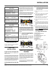
Note:
a) The horizontal run of vent must be level,
or have a 1/4 inch rise for every 1 foot
of run towards the termination. Never
allow the vent to run downward. This
could cause high temperatures and
may present the possibility of a fi re.
b) The location of the horizontal vent
termination on an exterior wall must
meet all local and national building
codes, and must not be blocked or
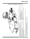
obstructed. For External Vent Terminal
Locations, see diagram in the "Exterior
Vent Termination Locations" section.
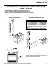
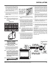
6) The arrow on the vent cap should
be pointing up. Insure that the 1-1/2"
clearances to combustible materials are
maintained (Diagram 3 in the "Venting
Arrangement - Horizontal Terminations"
section) Install the termination cap.
The four wood screws provided should
be replaced with appropriate fasteners for
stucco, brick, concrete, or other types of
sidings.
Note: If installing termination on a siding
covered wall, a vinyl siding standoff
or furring strips must be used to
ensure that the termination is not
recessed into the siding.
Note: Apply sealant "Mill-Pac" to inner
pipe and high temperature silicone
sealant to outer pipe on every twist-
lock joint.
b) Horizontal runs of vent must be
supported every three feet. Wall straps
are available for this purpose.
5) Mark the wall for a 10" x 10" square hole.
The center of the square hole should line
up with the centerline of the horizontal pipe.
Cut and frame the 10 inch square hole in
the exterior wall where the vent will be
terminated. If the wall being penetrated is
constructed of non-combustible material, i.e.
masonry block or concrete, a 7"(178mm)
dia. (7-1/2"(191mm) dia. for fl ex) hole is
acceptable.
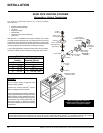
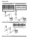
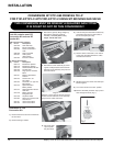
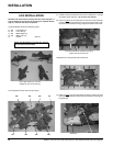
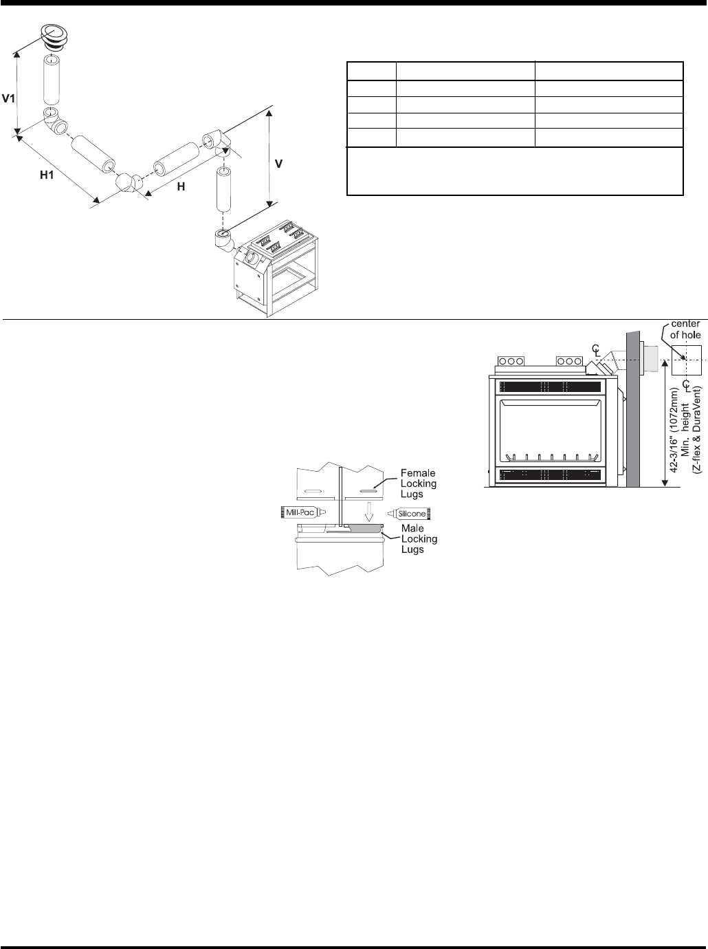
Note: With Dura-Vent, the minimum height
is achieved by installing a 45
o
elbow directly
to the rigid pipe adaptor.
Diagram 12
Vertical Venting with Three (3) 90
o
Elbows
ends, Diagram 1. Push the pipe sections
completely together, then twist-lock
one section clockwise approximately
one-quarter turn, until the two sections
are fully locked. The female locking lugs
will not be visible from the outside, on
the Black Pipe or fi ttings. They may be
located by examining the inside of the
female ends.
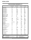
Option V + V1 H + H1
A) 2' (610mm) Minimum 3' (914mm) Maximum
B) 3' (914mm) Minimum 6' (1.86m) Maximum
C) 4' (1.22m) Minimum 9' (2.7m) Maximum
D) 5' (1.5m) Minimum 12' (3.6m) Maximum
With the above options, maximum total pipe length if 37 feet with minimum
of 5 feet total vertical and maximum 12 feet total horizontal.
Please note minimum 1 foot between 90
o
elbows is required.