


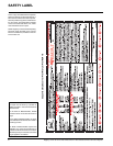
Regency
®
P121-2/P121LC-2/P121RC-2/P131-2 Zero Clearance Direct Vent Gas Fireplace
12
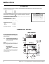
VENTING
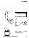
INTRODUCTION
The P121-2/P121LC-2/P121RC-2/P131-2 uses
the "balanced fl ue" technology Co -Axial system.
The inner liner vents products of combustion to
the outside while the outer liner draws outside
combustion air into the combustion chamber
thereby eliminating the need to use heated
room air for combustion and losing warm room
air up the chimney.
Note: These flue pipes must not be
connected to any other appliance.
The gas appliance and vent system must be
vented directly to the outside of the building,
and never be attached to a chimney serving a
separate solid fuel or gas burning appliance.
Each direct vent gas appliance must use it's
own separate vent system. Common vent
systems are prohibited. (See "Rigid Pipe Venting
Systems" for more details and exceptions).
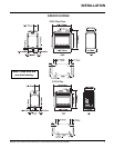
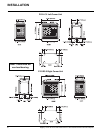
INSTALLATION
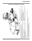
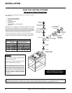
UNIT ASSEMBLY
PRIOR TO
INSTALLATION
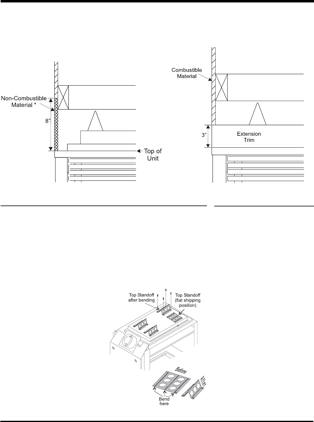
The 4 Top Standoffs must be correctly positioned and attached to the top before unit is slipped
into position.
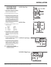
Top Standoff Assembly
The top standoffs are shipped in a fl at position and must be folded into shape and attached.
1) Remove the standoffs from the fi replace
top.
2) Take each standoff and bend into the correct
shape. Bend up at the bend lines until the
screw holes in the standoff and the pre-
punched screw holes on the fi replace top
line up.
3) Attach the standoff securely to the top with 4
screws per standoff (on opposite corners).
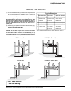
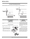
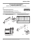
Facing & Finishing Requirements
This fi replace is supplied with a 3" metal extension trim above the fi replace. The extension trim may be replaced if the framing is faced with a non-
combustible material placed fl ush with the front and side face of the unit and extending from the top of the unit. (ie. tile, slate, etc.)