


Regency Insert & Hearth Heater 9
INSTALLATION
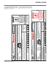
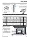
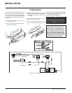
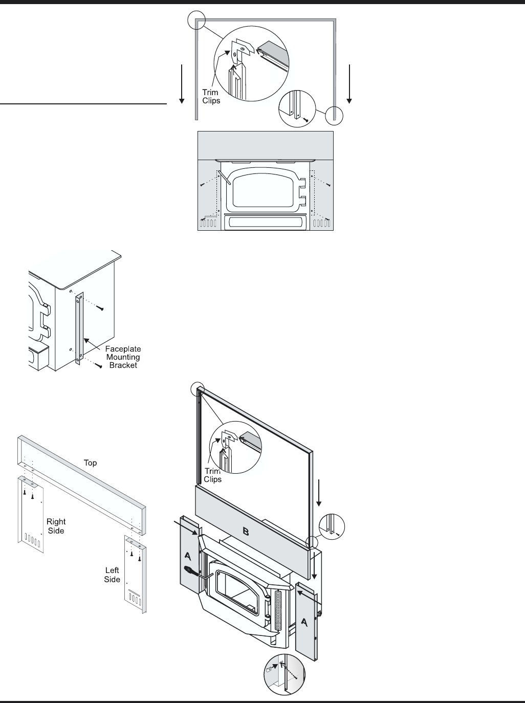
Diagram 4:
H2100M, I2100M
and I3100L
Faceplate
Assembly
3) Attach the assembled faceplate to the face-
plate mounting brackets.
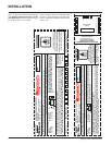
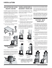
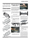
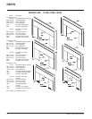
Diagram 2: I1100S
Rear View
Diagram 3: I1100S
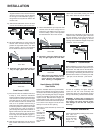
B) H2100M, I2100M and I3100L Inserts
1) Slide the spring nuts (supplied) over the
slots in the insert’s side convection panels
(the spring nuts may need to be squeezed
with a pair of pliers first, to help them stay
in position).
2) Screw the side faceplate panels, (item A in
diagram 4) one to each side.
3) Using the top panel (item B in the diagram) as
a gauge, check that the side panels are
within approximately 1/4" of the overall
width. If the difference is greater
than this, use the supplied
washers to attain the re-
quired width.
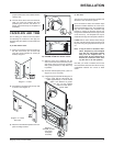
C) All units
The unit may now be slid into final position and
attached to the connection system.
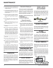
Once connection is made, the insulation strips
should be installed between the insert face-
plates and the fireplace face. The faceplate top
may now be installed (with insulation strip
behind) by aligning its brackets with the top
flange on the side shields and the angle iron bar
on the insert top. The faceplate trim may be
installed to the edge of the faceplate at this time.
I1100S: Drill two 5/32" diameter holes through
the trim and side panels and screw the trim to
the panels using the gold plated screws provid-
ed.
Note: It may be easier to install the insu-
lation, faceplate top and faceplate
trim with the unit pulled slightly
away from the fireplace face. If
this is done, be very careful not to
disturb the connector when shift-
ing the unit to its final position.
Now that your insert is installed, check once
more that all the clearances from the unit to any
combustible materials are correct as listed
earlier.
Diagram 1: I1100S
proper stainless steel unit available with the
chimney liner.
6) Once the above items have been checked,
slide your insert into position after first
positioning the flue liner and offset if re-
quired. (Re-install raincap at completion of
installation).
FACEPLATE AND TRIM
Prior to sliding your insert into its final position
and attaching the connector or liner pipe, the
faceplate side panel plates must be installed as
follows:
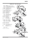
A) I1100S Small Insert
1) Fasten the faceplate mounting bracket to
the side of the insert (one on each side)
using the screws provided (2 screws per
bracket). Diagram 1.
2) Assemble the faceplate sides and top with
4 screws. See Diagram 2.