


Regency Insert & Hearth Heater8
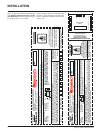
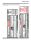
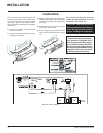
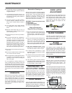
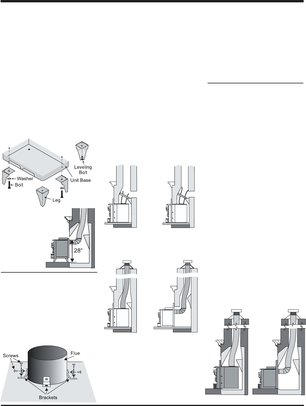
1) Positive Flue
Connection
with Cleanout
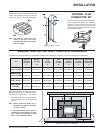
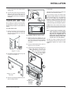
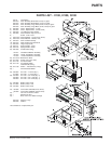
FLUE CONNECTOR
BRACKET
Package contains: 3 brackets and 6 screws.
These brackets are to be used to hold the flue
liner (not supplied) to the Insert and keep the
connection. The brackets are screwed into the
top of the Insert in the pre-punched holes and
then screwed into the flue liner.
INSTALLATION INTO A
MASONRY FIREPLACE
The insert must be installed as per the require-
ments of your local inspection authority. Three
methods of flue connection are acceptable in
most areas, these include:
1) Positive flue connection, where a large
blocking plate and a short connector pipe is
used.
2) Direct flue connection, where a smaller
blocking plate and a connector pipe to the
first flue liner tile is used.
3) Full flue liner, where a stainless steel rigid
or flexible liner pipe is routed from the insert
outlet collar to the top of the chimney.
Regency highly recommends the use of a full
liner as the safest installation and provides the
most optimum performance. Your retailer should
be able to help you decide which system would
be the best for your application.
Flush Inserts Hearth Heater
INSTALLATION
2) Direct Flue
Connection
with Cleanout
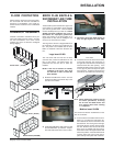
3a)Full Flue Liner
(No Cleanout
Required)
3b)Hearth Heater with
Full Flue Liner
(No Cleanout
Required)
Note: A clean-out door is sometimes
required, by your inspector, to be
installed when either the Positive
flue connection or Direct flue con-
nection method is used.
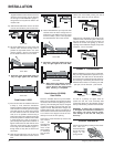
NOTE: Adding the legs
changes the height of
the unit, make sure you
have sufficient clear-
ance (min. 28") for your
flue connection.
LEG OPTION ON H2100
HEARTH HEATER
The addition of legs to the Hearth Heater does
not alter its certification, it does not become a
freestanding woodstove. The H2100 can only
be installed as a Hearth Heater i.e. vented into
a masonry or factory built fireplace.
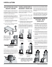
The instructions below apply to the steel leg,
painted cast leg and the gold plated cast leg. It
will be easier to attach the legs to the stove if
it is tipped on its back (preferably on a soft
surface to prevent scratching).
1) Thread the bolt and washer through the
leg, and then into the nutsert in the base
of the stove and tighten.
2) Level the stove by adjusting the levelling
bolts in the bottom of each leg.
The use of one of the connection methods
listed on this page not only increases the safety
of your insert by directing the hot gases up the
flue, but will also help increase the unit's
efficiency and decrease creosote deposits in
the chimney.
When a connected flue or liner is in use, the
insert is able to “breathe” better by allowing a
greater draft to be created. The greater draft
can decrease problems such as, difficult start-
ups, smoking out the door, and dirty glass.
INSTALLATION INTO A
FACTORY BUILT
FIREPLACE
1) When installed in a factory built fireplace,
a full stainless steel rigid or flexible flue liner
is mandatory, for both safety and perform-
ance purposes. When a flue or liner is in
use, the insert is able to breathe better by
allowing a greater draft to be created. The
greater draft can decrease problems such
as, difficult start-ups, smoking out the door,
and dirty glass.
2) In order to position the flue liner, the existing
rain cap must be removed from your chim-
ney system. In most cases the flue damper
should also be removed to allow passage
of the liner.
3) In most cases opening the existing spark
screens fully should give enough room for
the insert installation. If it does not, remove
and store.
4) If the floor of your fireplace is below the
level of the fireplace opening, adjust the
insert's levelling bolts to accommodate the
difference. When additional shimming is
required, use non-combustible masonry or
steel shims.
5) Measure approximately the alignment of
the flue liner with the position of the smoke
outlet hole on the insert to check for pos-
sible offset. If an offset is required, use a