


Regency Insert & Hearth Heater 7
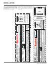
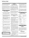
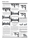
Clearance diagram for installations
INSTALLATION
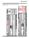
Side and Top facing is a maximum of 1.5" thick.
Floor protection must non-combustible, insula-
tive material with an R value of 1.1 or greater.
* If the hearth extension is flush with the floor
(F) it must extend 19.5" in front of the body
face (E).
Note: Hearth Extension Width (G) is
measured from edge of fuel door
to side of hearth.
** A non-combustible mantel may be
installed at a lower height if the fram-
ing is made of metal studs covered
with a non-combustible board.
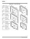
MASONRY AND FACTORY BUILT FIREPLACE CLEARANCES
The minimum required clearances to combustible materials when installed into a masonry or factory built fireplace are listed below.
Adjacent Mantle** Top Side Minimum Minimum Minimum
Unit Side Wall (to Top) Facing Facing Hearth Hearth Hearth Side
(to Side) (to Top) (to Side) Extension* Thickness* Extension
AB C DEFG
Small Flush
Insert (I1100S) 15"/380mm 20"/510mm 14"/355mm 7.375"/187mm 16"/406mm 1.5"/38mm 8"/205mm
Medium Flush
Insert (I2100M) 10"/255mm 17"/430mm 10.25"/260mm 8"/203mm 16"/406mm 1.5"/38mm 8"/205mm
Large Flush
Insert (I3100L) 13"/330mm 19"/480mm 18"/455mm 6.5"/165mm 16"/406mm 1.5"/38mm 8"/205mm
Hearth Heater
(H2100M) 10"/255mm 25"/635 mm 14"/355mm 8.5"/216mm 18"/455mm 1.5"/38mm 6"/152mm
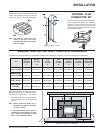
View from Rear of Insert
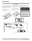
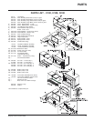
OPTIONAL FLUE
CONNECTOR KIT
The optional Flue Connector Kit (Part # 846-527)
and the Straight Flue Adaptor (Part #846-504)
shown here, may be used to produce a secure
connection between your flue connector and
the insert collar. Detailed installation instructions
are included with the kit.
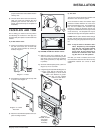
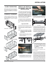
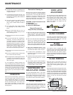
Position the grill on the inside bodyface side and
fasten using the bolts, washers and nuts pro-
vided (2 per side) as shown in the diagrams.
Note: The grill has a front and rear, the
holes on the front side have
rounded edges and the rear holes
have flat edges.