


HZ54 Regency Horizon
TM
Gas Fireplace
32
INSTALLATION
INSTALLATION
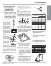
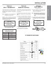
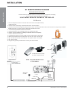
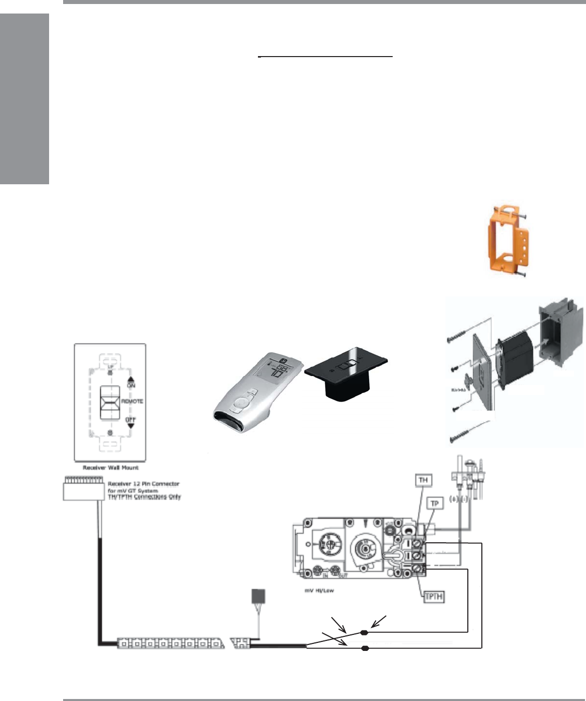
GT REMOTE WIRING DIAGRAM
Red wire
Black wire
Green wire
Extra wires
not used
White wire
spade connectors
J-Box
Receiver
Wall Plate
Slider Switch
Low Voltage Junction Box
REFER TO CODING INSTRUCTIONS
IN THIS MANUAL
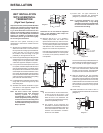
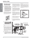
IMPORTANT INSTALLATION NOTE:
The SIT Profl ame GT REMOTE Receiver must be placed inside the supplied (Low Voltage)
junction type wall box and installed into the wall only.
DO NOT INSTALL WITHIN THE CONFINES OF THE FIREPLACE.
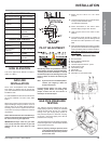
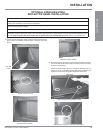
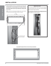
Wall Mounting
1. Add two male spade connectors to the end of the 10 foot 2-wire harness (Black & Red)
installed with HZ54.
2. Install the J-Box to the framing, at desired location within 10ft from fi replace.
3. Feed the 2ft wire harness through the opening at back of J-Box, Connect the black & red wires to the two wires from the (2 foot) SIT Profl ame
GTMF wire harness, (TH green) & (TP/TH White) other wires will not be used.
4. Connect the wiring harness to the back of the receiver.
5. Install the Receiver in the Low Voltage Junction box, supplied with HZ54.
6. Insert the 4 AA type batteries in the battery compartment with the correct polarity.
7. Place the slider into the cover plate.
8. Put the Receiver switch in the “OFF” position, to allow correct lineup for slider switch.
9. Make sure the Receiver and cover plate words “ON” and “UP” are on the same side.
10. Align the slider with the switch on the Receiver and couple the switch into the slider.
11. Align the screw holes.
12. Using the two (2) screws provided secure the cover plate to the Receiver.
FPI Wall Switch & Cover Plate
are white, not black as shown.