


HZ54 Regency Horizon
TM
Gas Fireplace 31
INSTALLATION
INSTALLATION
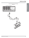
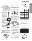
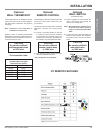
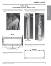
Optional
WALL SWITCH
(Included with Unit)
1) Run the supplied 10' of wire through the
right or left side gas inlet opening. Be
careful not to damage wire.
Note: We recommend a maximum of 10'
of wire but if you wish to go with a
longer run, use the Thermostat Wire
Table.
2) Connect the wire to the wall switch and
install into the receptacle box (supplied).
Also attach wires to the valve as shown
below.
CAUTION
Do not wire millivolt
wall switch wire
to 120V wire.
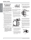
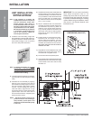
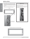
Optional
WALL THERMOSTAT
A wall thermostat may be installed if desired,
connect the wires as per the wiring diagram.
Use table below to determine the maximum
wire length.
Note: Preferable if the thermostat is
installed on an interior wall.
Regency
®
offers an optional programmable
thermostat but any 250-750 millivolt rated non-
anticipator type thermostat that is CSA, ULC or
UL approved may be used.
CAUTION
Do not wire millivolt
wall thermostat wires
to 120V wire.
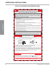
Thermostat Wire Table
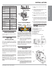
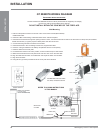
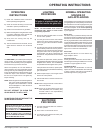
Optional
REMOTE CONTROL
Use the Regency
®
Remote Control Kit approved
for this unit. Use of other systems may void
your warranty.
The remote control kit comes with a hand held
transmitter, a receiver and a wall mounting
plate.
1) Choose a convenient location on the wall
to install the receiver and the receptacle
box (protection from extreme heat is very
important). Run wires from the fi replace to
that location. Use Thermostat Wire Table.
CAUTION
Do not wire millivolt
remote control wires
to 120V wire.
2) See optional remote control instruction
manual for detailed instructions.
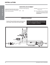
* See next page for wiring diagram.
14 GA.
16 GA.
18 GA.
20 GA.
22 GA.
50 Ft.
32 Ft.
20 Ft.
12 Ft.
9 Ft.
Recommended Maximum Lead Length
(Two-Wire) When Using Wall
Thermostat (CP-2 System)
Wire Size Max. Length
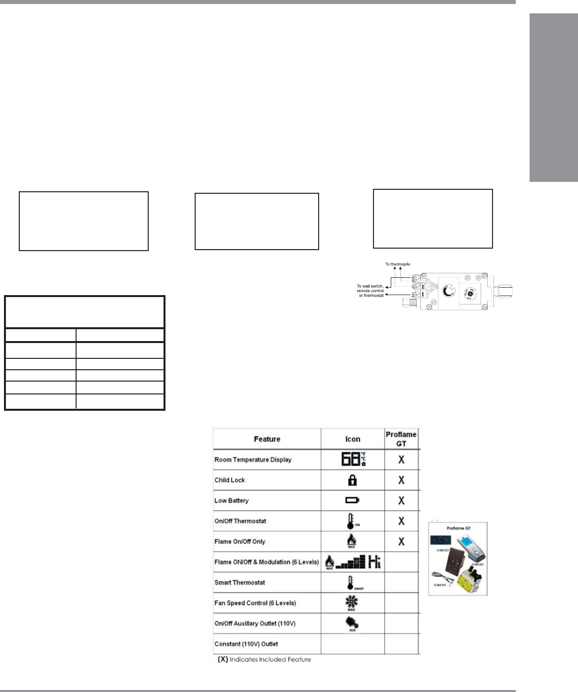
GT REMOTE FEATURES