


HZ54 Regency Horizon
TM
Gas Fireplace 13
INSTALLATION
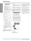
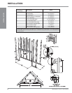
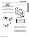
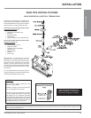
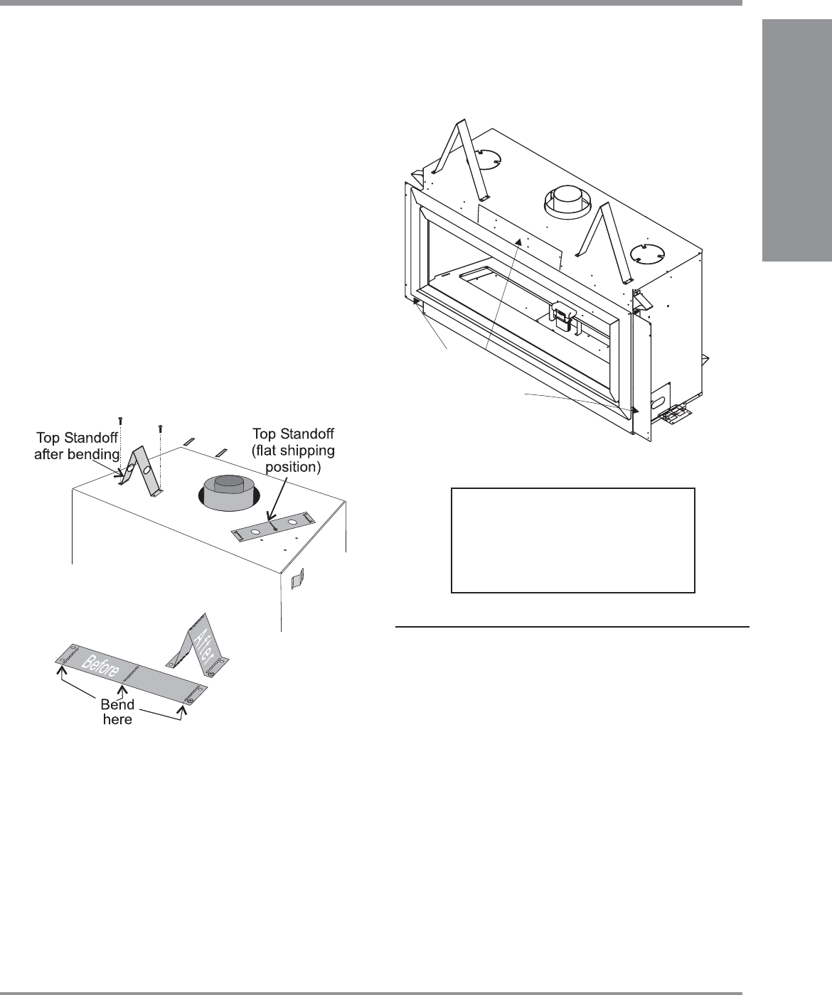
SIDE NAILING STRIPS
The side and top nailing strips come attached to the unit. There is 1 plate
on each side, and 1 on the top, that can be folded out as required.
Nailing Strips
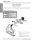
UNIT ASSEMBLY
PRIOR TO
INSTALLATION
The Top Facing Support, the Side Nailing Strips and the 2 Top Standoffs
must be correctly positioned and attached to the top before unit is
slipped into position.
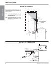
TOP STANDOFF ASSEMBLY
The top standoffs are shipped in a fl at position and must be folded into
shape and attached.
1) Remove the standoffs from the fi replace top.
2) Take each standoff and bend into the correct shape. Bend up at the
bend lines until the screw holes in the standoff and the pre-punched
screw holes on the fi replace top line up.
3) Attach the standoff securely to the top with 2 screws per standoff
(on opposite corners).
Nailing Strips shown folded out.
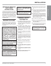
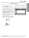
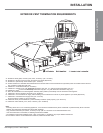
VENTING INTRODUCTION
The HZ54 uses the "balanced fl ue" technology Co Axial system. The
inner liner vents products of combustion to the outside while the outer
liner draws outside combustion air into the combustion chamber thereby
eliminating the need to use heated room air for combustion and losing
warm room air up the chimney.
Note: These fl ue pipes must not be connected to any other
appliance.
The gas appliance and vent system must be vented directly to the outside
of the building, and never be attached to a chimney serving a separate solid
fuel or gas burning appliance. Each direct vent gas appliance must use
it's own separate vent system. Common vent systems are prohibited.
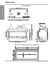
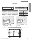
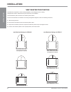
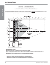
IMPORTANT NOTE
Framing depth measurement is noted with the
side nailing strips set as far forward on the
fi rebox as possible. The side nailing strips can
be adjusted back up to 1” to allow for varying
thicknesses in non-combustible material & wall
fi nishes.
INSTALLATION