


57
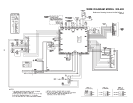
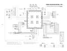
PILOT TURN DOWN TEST FOR RAYPAK HI DELTA BOILERS
The Hi Delta boilers, depending on their size, have from two to five burner sections. Each burner section is supplied gas
by dual gas valves incorporated in single valve body. A maximum of three burner sections may be controlled by a single
hot surface ignition system. The middle of the three burner sections is lighted directly with a hot surface ignition system.
The burner section that is ignited directly by the hot surface ignition system serves as a supervised pilot to light the
burner sections on either side of it. The burner sections on either side of the supervised section (pilot) are electrically
interlocked with the supervised ignition system so as to not be energized unless flame is proven on the center section
which is acting as a pilot to light the right and left hand sections.
The pilot turn down test is conducted as follows:
1) Turn off manual valves on non-supervised burner sections.
2) Turn on electrical power and adjust thermostat to call for heat.
3) Wait for completion of ignition sequence to light burner section being utilized as a pilot for those turned off in (1)
above.
4) Gradually reduce manifold pressure (flame) on supervised burner section by closing manual gas valve. Watch
for shut down due to loss of supervised flame signal as pressure is being reduced. Flame signal should be lost
before manifold pressure goes below 2 inches water column.
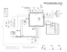
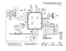
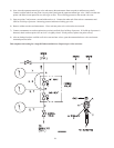
LEAK TEST PROCEDURE: DUAL-SEAT GAS VALVES
Proper leak testing requires three pressure test points in the gas train.
Test point A is upstream of the automatic gas valve. On the first automatic valve, this is a bleedle valve. On the
other valves, this is a plugged port. The bleedle valve on the first valve may be used for all the other valves as
well.
Test point B is a bleedle valve located between the two automatic gas valve seats.
Test point C is located downstream of both automatic gas valve seats and upstream of the manual valve. On the
manual valve, this is a bleedle valve. Identical readings will be found at the plugged port labeled as Alternate C”.
Refer to attached diagrams. Numbers on the diagram refer to the steps below:
These tests are to be conducted with the electrical power to the boiler turned off.
1) Manually close the downstream leak test valve.
2) Open test point A and connect a manometer to it. Verify that there is gas pressure and that it is within the proper
range (note: must not exceed 14 inches water column).
3) Open test point B and connect a rubber tube to it. Connect the other end of the tube to a manometer and look for a
build u of pressure. Increasing pressure indicates a leaking gas valve.