


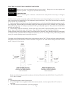
ELECTRICAL CONNECTIONS - DOMESTIC HOT WATER
CAUTION: Label all wires prior to disconnection when servicing controls. Wiring errors can cause improper and
dangerous operation. Verify proper operation after servicing.
DANGER - SHOCK HAZARD
Make sure electrical power to the heater is disconnected to avoid potential serious injury or damage to
components.
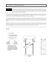
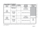
Installer action is required to electrically enable your Hi-Delta boiler to operate after making the power conections. You must
make a connection on Terminal Block #3 for temperature control connections. This will be done based on the controller
option selected with your boiler order.
1. For Pool and Closed Loop Water Source Heat Pump applications, your boiler should be configured to operate in an ON/
OFF firing mode. This means that you will connect a single-pole control to stage one of TB-3 (Terminals 1&2). Then jumper
the remaining firing stages. For example, if your boiler is a 652, you will jumper stage two. Then your boiler will either be on
at full fire, or it will be off.
2. For multi-stage controller connections, connect each stage of the control to the corresponding stage of TB-3 in the
boiler. Stage 1 of the boiler to stage 1 of the control. Stage 2 of the boiler to stage 2 of the control, and so on.
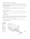
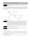
Set the operating control at the setpoint in which you want the boiler to maintain. Ensure that the sensing bulb of the control
is at the point in the system that will best maintain the temperature you want. For example, when you are heating a tank of
water, you want the operating control sensor bulb in the tank.
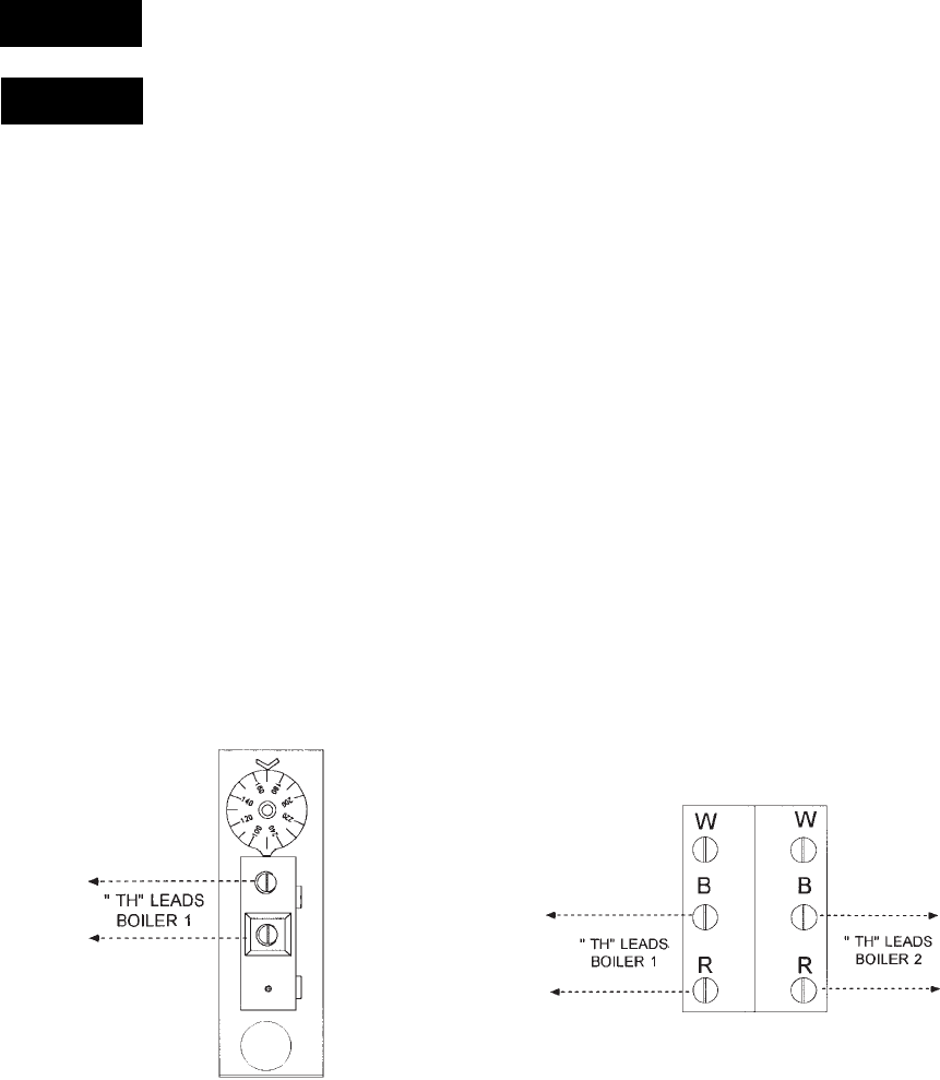
Consult the wiring diagram shipped with the boiler in the instruction packet. The "TH" leads are for the remote tank control
through the boilers 24 volt transformer. DO NOT attach line voltage to the "TH" leads. Before starting boiler check to insure
proper voltage to boiler and pump.
23
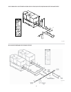
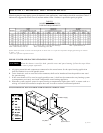
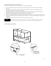
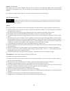
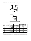
NOTES:
1. Field installed ground to inside of junction box.
2. If any of the original wire as supplied with the boiler must be replaced, it must be replaced with 105°C wire or its
equivalent.
3. “TH” leads connect to terminal block 3 (See wiring diagram).
Fig. #9138.2
2-STAGE
TANKSTAT
ig. #9138.1
BREAK THE WIRE NUT AT THE
BOILER "TH" CONNECTIONS AND
ATTACH TO THE DUAL TANKSTAT
PER ILLUSTRATION
BREAK THE WIRE NUT AT THE
BOILER "TH" CONNECTIONS AND
ATTACH TO THE SINGLE TANKSTAT
PER ILLUSTRATION
SINGLE
STAGE
TANKSTAT
Boiler must be electrically grounded in accordance with National Electrical Code ANSI/NFPA No. 70, and CSA C22.1
C.E.C. Part 1 in Canada.