


HI-DELTA Model 502-752
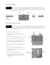
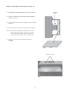
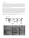
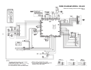
The black (hot) wire leads you directly to the Main Power Switch. This switch is located at the bottom right-front corner of
the control compartment. When the main power switch is placed in the “ON” position, both the 120 v and 24 v terminal blocks
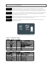
on the Main Circuit Board will be powered and the power light will turn on. When the Auto On- Off switch is turned ON, the
following 24 v safety components are immediately energized: Low Water Cut-off, Blocked Vent Switch, Manual Reset Limit
Control, Low Gas Pressure Switch (optional) and the High Gas Pressure Switch (optional). At this point if all the preceding
safety switches are closed, then Relay K 1 (n.c.) will be energized and the safety light will turn off. The boiler is now ready
for a call for heat.
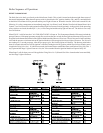
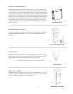
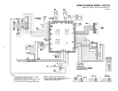
When STAGE 1 calls for heat, the CALL FOR HEAT LIGHT will turn on. The Economaster Board will be energized and the
pump will turn on. If the pump generates enough flow to activate the flow switch, the flow light will turn on, then power will
be applied to the thermostat terminal of the Ignition Module and the Blower will activate.The Air Pressure Switch will close,
and the pressure switch terminal on the Ignition Module will be energized the blower light will turn on. The Unit will now
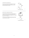
undergo a 15 second pre-purge. After the pre-purge cycle, Hot Surface Igniter will heat up. The heat-up period takes about
30 seconds after which a trial for ignition is initiated. During the trial for ignition, which lasts for four seconds, power is
applied to Firing Valve No. 1. If within four seconds, the Remote Sensor establishes flame rectification, the Firing Valve No.
1 stays open and the Stage 1 light will turn on. Also, the Valve terminal from the ignition Module will power Relays K2, and
K3.
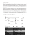
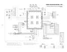
When Stage 2 calls for heat, power will pass through the Time Delay Relay, then after 10 seconds through Relay K2, and then
applied to Firing Valve No. 2, and the Stage 2 light will turn on.
45