


CIRCUIT
BREAKER
WHITE
GROUND
BLACK
GREEN
ABC
VOLT-OHM
METER
SECTION I: ELECTRICAL POWER CONNECTIONS
Installations must follow these codes:
· National Electrical Code and any other national, state, provincial or local codes or regulations having
jurisdiction.
· Safety wiring must be N.E.C. Class 1.
· Boiler must be electrically grounded as required by N.E.C. ANSI/NFPA 70-latest edition.
· In Canada, C.S.A. C22. 1 C.E.C. Part 1.
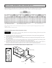
The boiler is wired for 120 Volts, 12 AMPS. The voltage is indicated on the tie-in leads. Consult the wiring diagram shipped
with the boiler in the instruction packet. The remote tank control stat, thermostat, or electronic boiler control as applicable,
may be connected to the stage selector terminal (See wiring diagram). 24 Volts are supplied to this connection through the
boiler transformer. DO NOT attach line voltage to the “TH” leads. Before starting the boiler check to insure proper voltage to
the boiler and pump.
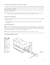
FIELD-CONNECTED CONTROLLERS
Install a separate disconnect means for each load. Use appropriate-sized wire as defined by NEC, CSA and/or local code. All
primary wiring should be 125% of minimum rating.
It is strongly recommended that all individually-powered control modules and the boiler should be supplied from the same
power source.
SURGE PROTECTION
Microprocessor-based and solid state controls are vulnerable to damage from voltage and amperage fluctuations in the
power supply. All sensitive control components should be protected by a suitable commercial-grade surge protection device.
If any of the original wire as supplied with the boiler must be replaced, it must be replaced with 105°C wire or its equivalent.
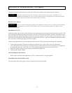
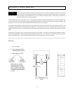
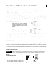
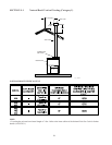
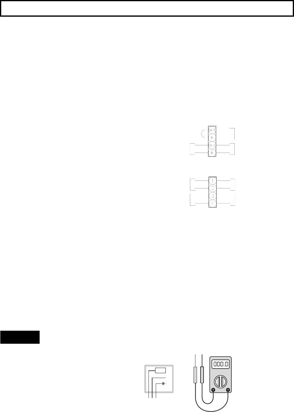
CHECK THE POWER SOURCE
WARNING: Using a volt-ohm meter (VOM), check the following voltages at the circuit breaker panel prior to
connecting any equipment: Make sure proper polarity is followed and house ground is proven.
FIGURE I-1
CHECK POWER SOURCE
AC = 108 Volts AC Minimum, 132 Volts AC MAX
AB = 108 Volts AC Minimum, 132 Volts AC MAX
21
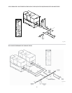
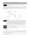
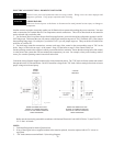
Fig. # 9237
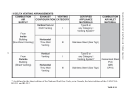
If unit does not have a factory wired stage
controller, the unit is factory-wired in On/Off
configuration with other stage terminals
jumpered.
To field-connect stage controller, remove fac-
tory-installed jumper and wire stage control
as shown.
Stage Selector
Stage Selector
Stage 2
Stage 2
Stage 1
Stage 1
Control
Stage 2
Control
Stage 1
Factory
Jumpered
Control
ON/OFF
2-STAGE