5100-I ACT WOOD INSERT
April 21, 2010
R
438-0380E
at the factory with the power cord on right side of insert (as
you face the unit). Do not route the power cord under or in
front of appliance.
instructions below.
B. Blower Cord Location
receptacle.
• Route cord away from appliance.
•
of appli-
ance.
CAUTION
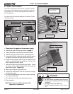
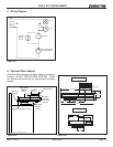
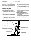
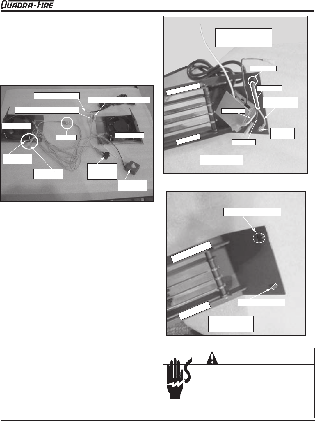
Figure 12.1 - Blower Assembly Components
Snap Disc
Snap Disc
by-pass
switch
Speed Control
(Rheostat)
Right Blower
Left Blower
Red
Connector
Blue
Connector
White wire into Red Connector
Black wire into Blue Connector
Green grounding wire
Grounding
screw
Green
grounding wire
Blower cord
Black wire
White wire
Strain Relief
Bottom of grille
Top of grille
Back view of grille
Blower cord attached to
right side of grille.
Remove button plug
Grounding screw
Back view of left
side of grille
Bottom of grille
Top of grille
1. Disconnect the appliance from power supply.
2. Remove the grille following instructions on page 11.
4. Remove green grounding wire from grounding screw.
the blower cord wires and strain relief from the grille.
-
catcher on the left side of the appliance. Cut the zip tie
that is holding the wires in place.
the blower cords wires through the hole and snap the
strain relief in place. Figure 12.3.
8. Attach grounding wire to ground screw.
9. Connect the white blower cord wire to the red connector
on the wire harness.
-
tor on the wire harness.
12. Re-install grille.
Figure 12.2
Figure 12.3
NOTE: Each wire has a label to denote which
component it connects to.


