


27
INSTRUCTIONS PERTAINING TO THE INSTALLER 926.772.1 - GB/IE
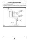
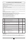
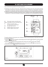
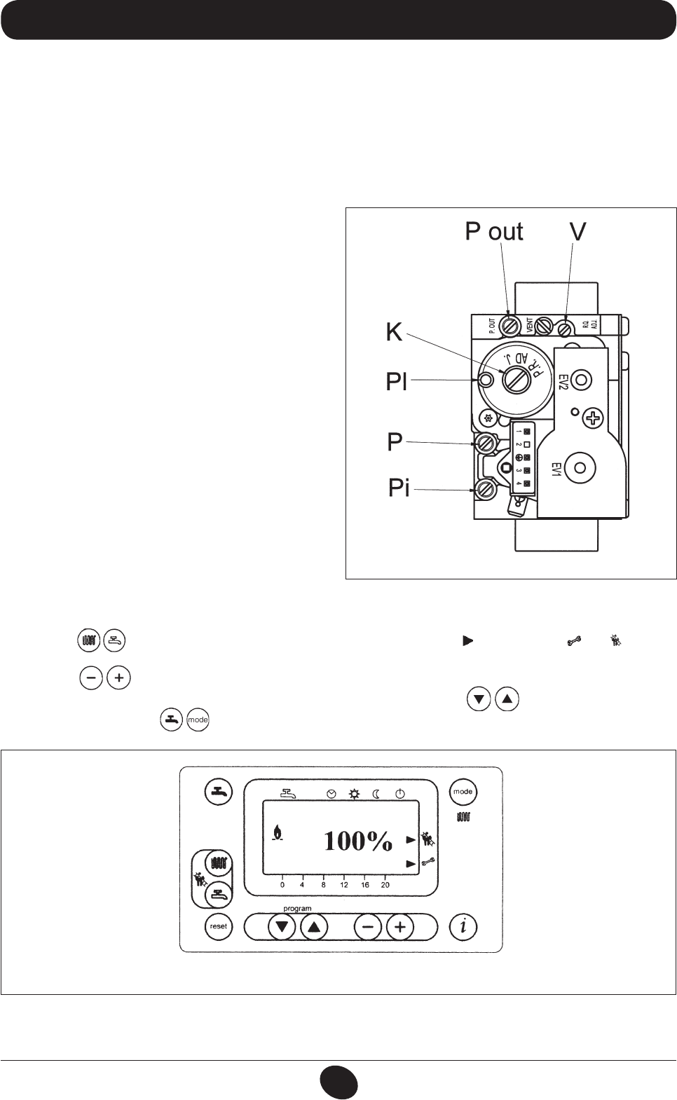
To simplify calibration of the gas valve, the “calibration function” can be set directly on the boiler control panel
by proceeding as follows:
1) Press the keys (2-3) together until the display shows the pointer “ ” alongside the and symbols
(about 6 seconds) (see g. 16).
2) Press the keys to set the fan speed at the minimum and maximum heat output (%PWM);
N.b - to set the minimum and maximum heat output quickly, press the keys respectively;
3) press either of the two keys to exit the function.
0307_2201
Figure 16
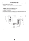
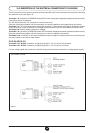
Pi: Gas supply pressure connection point
P out: Gas pressure to burner connection point
P: Pressure connection point
for measurement of the OFFSET
Pl: Air signal input from fan
V: Gas ow adjuster screw max re
K: OFFSET adjuster screw min re
0310_0114
Figure 15
15. GAS VALVE ADJUSTMENT
Carry out the following ope rations in the given sequence:
1)
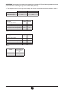
Calibration of the maximum heat output. Check that the CO
2
measured on the ue, with the boiler operating
at the maximum heat output, is the same as that shown in table 1. Otherwise, turn the regulation screw (V) on
the gas valve. Turn the screw clockwise to reduce the concentration of CO
2
and anticlockwise to increase it.
2) Calibration of reduced heat output. Check that the CO
2
measured on the ue, with the boiler operating at the
minimum heat output, is the same as that shown in table 1. Otherwise, turn the offset regulation screw (K) on
the gas valve. Turn the screw clockwise to increase the concentration of CO
2
and anticlockwise to reduce it.