


12
INSTRUCTIONS PERTAINING TO THE INSTALLER 926.772.1 - GB/IE
To avoid damaging metal, plastic and rubber parts, use only neutral cleaners, i.e. non-acid and non
alkaline. The recommended products for cleaning are:
SENTINEL X300 or X400 and FERNOX heating circuit restore. Please ensure to use this product
proceeding strictly in accordance with the manufacturers instructions. Finally ll the system with the
correct strength of central heating inhibitor.
2.2. Existing system
Before proceeding with installation of the boiler, the system must be cleaned and ushed out to remove
sludge and contaminants, using suitable proprietary products as described in section 2.1.
To avoid damaging metal, plastic and rubber parts, use only neutral cleaners, i.e. non-acid and non-
alkaline such us SENTINEL X100 and FERNOX heating circuit protective. To use this product proceeding
strictly in accordance with the maker’s directions.
Remember that the presence of foreign matter in the heating system can adversely affect the operation
of the boiler (e.g. overheating and noisy operation of the heat exchanger). Dose with inhibitor.
Failure to observe the above will render the guarantee null and void.
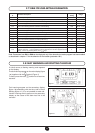
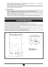
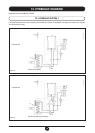
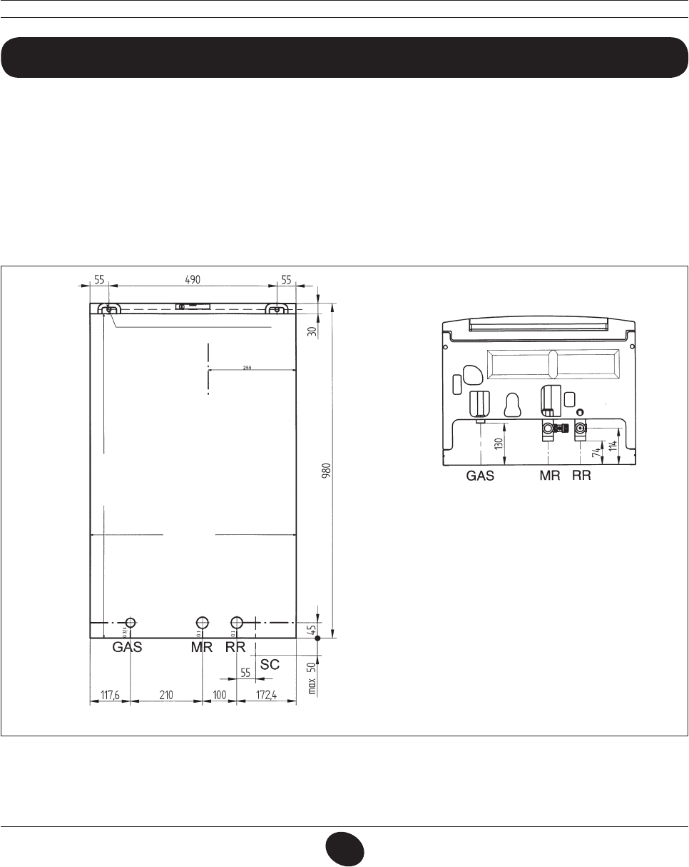
10. BOILER INSTALLATION
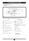
Decide upon the boiler location, then tape the template on the wall.
Connect the pipework to the gas and water inlets prearranged on the template lower bar.
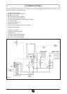
If you are either installing the boiler on a pre-existing system or replacing it, we suggest you also t strainers
on the system return pipework to the boiler to collect the deposits and scaling which may remain and be
circulated in the system after the initial lling.
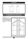
When the boiler is xed on the template connect the ue and air ducts (ttings supplied by the manufacturer)
according to the instructions given in the following relevant sections.
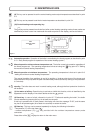
Connect the condensate outlet to the siphon supplied with the boiler. Connect the siphon to a drain, making
sure there is a continuous slope. Horizontal sections must be avoided.
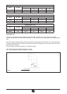
MR: G 1” heating ow
GAS: G 3/4” gas inlet to the boiler
RR: G 1” heating return
SC: condensation drain 22 mm
Figure 5
0506_0806
DRILL HOLES WITH A Ø12 BIT, FIT THE MASONRY
PLUGS AND THE SCREWS PROVIDED
FLUE AXIS
N.B. INCLUDE CONDENSATE DRAIN POINT
BOILER HEIGHT 950
BOILER WIDTH 600
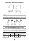
gas inlet to the boiler
heating ow
heating return
condensation drain
0602_0701/CG_1469/1