


23
INSTRUCTIONS PERTAINING TO THE INSTALLER 926.772.1 - GB/IE
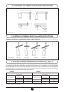
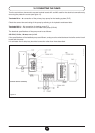
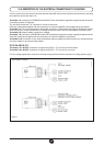
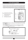
Turn the control box downward to access terminal board M2 used for the electrical connections by removing
the protective cover (see gure 13).
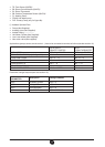
Terminals 1-2: connection of SIEMENS model QAA73 room temperature regulator supplied as optional extra.
Connection polarity is irrelevant.
The link tted across the “TA” terminals 3-4 must be removed.
Read the instructions supplied with this accessory for correct installation and programming procedures.
Terminals 3-4: “TA” room temperature thermostat connection. Thermostats with integral accelerator resistor
must not be used. Check that there is no voltage across the ends of the two thermostat connection wires.
Terminals 5-6: external safety contact (low voltage).
Terminals 7-8: connection of SIEMENS model QAC34 outdoor temperature sensor supplied as optional extra.
Read the instructions supplied with this accessory for correct installation procedures.
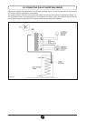
Terminals 9-10: connection of hot water temperature sensor supplied as optional extra for connecting hea-
ting-only boilers to an external water heater.
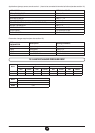
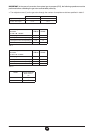
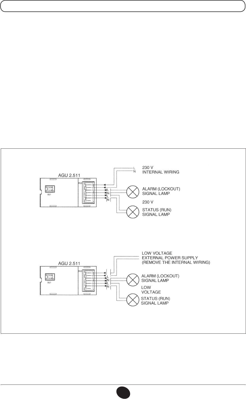
CLIP-IN AGU 2.511
Terminals 3-4 L-N OUT: connection to signal lamp (230 V - 0,5 A max) for lockout alarm.
Terminals 5-6 L-N OUT: connection to signal lamp (230 V - 0,5 A max) for run mode.
For low voltage signal lamp remove the internal wiring and feed with an external low voltage power supply.
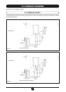
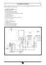
14.3 DESCRIPTION OF THE ELECTRICAL CONNECTIONS TO THE BOILER
Figure 14
0602_0708/CG1765
(OPTIONAL EXTRA)