


C3406M-D (1/07) 19
Extended dynamic range:
Use for extremely high dynamic installations, for example, doorways,
entrances, and exits. This profile offers the maximum wide dynamic range.
Fluorescent:
Use for any installation with flickering lighting of any kind.
NOTE:
If you select the Fluorescent profile, you should enable AC line lock for best results.
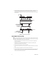
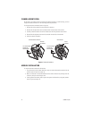
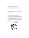
VERTICAL PHASE ADJUSTMENT (24 VAC OPERATION ONLY)
When using more than one camera power supply, a brief vertical roll may occur on the monitor when
switching from one camera to another.
To eliminate vertical roll, reverse the 24 VAC connections on one camera. If both cameras are
connected to the same transformer, this should solve the problem. If the problem still exists, adjust
the phase control by synchronizing, or line-locking, the cameras to one another.
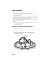
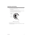
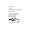
ADJUSTING THE VERTICAL PHASE
You may need two people when synchronizing the cameras: one at the camera, the other at the
monitor to observe the vertical roll and the effect of any camera adjustments.
To synchronize the cameras:
1. Choose a reference camera to which all other cameras will be phased.
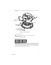
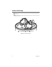
2. Select the camera to synchronize. Use the phase adjustment control (R8) to synchronize the
camera to the reference camera (refer to Figure 11). Turn R8 clockwise to increase vertical
phase; turn R8 counterclockwise to decrease vertical phase.
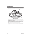
3. Each time an adjustment is made, switch back and forth between the camera you are
adjusting and the reference camera. Repeat this process as many times as necessary until the
roll between the cameras is no longer noticeable.
4. Adjust the phase of all other cameras by repeating steps 2 through 3. Always adjust to the
reference camera selected in step 1.
NOTE:
The preferred method for camera phase adjustment is to use a dual trace oscilloscope to
align the vertical sync pulses of the reference camera to the selected camera(s).
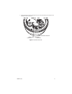
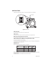
Figure 11.
Vertical Phase Adjustment
R8 R7 (RESERVED)