


C3406M-D (1/07) 11
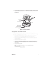
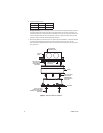
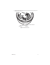
404 PLASTER RING INSTALLATION
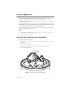
NOTE:
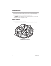
You should install the camera module into the back box before installing the back box into the
cover. When installing the back box into the cover, rotate the camera module to access the mounting
holes. Refer to
Camera Module
on page 14 for more information.
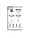
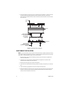
1. Remove the two 8-32 x 0.375-inch Phillips pan head screws and washers to separate the
cover from the back box.
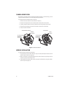
2. Pull video and power wires into the cover. Use up to three supplied 6-32 x 0.75-inch Phillips
pan head screws or two supplied 8-32 x 0.75-inch Phillips pan head screws to attach the cover
to an installed 404 plaster ring. Use stainless steel hardware when installing the system
outdoors.
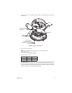
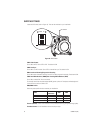
3. Connect the video cable/wires:
BNC:
Connect the BNC connector from the unit to a mating BNC connector.
Twisted Pair (UTP):
Blue wire = Video +
Gray wire = Video -
4. Connect the power wires.
AC operation only:
If you are wiring more than one Camclosure integrated camera system to
the same transformer, connect one side of the transformer to the red wire on all units, and
connect the other side of the transformer to the black wire on all units. Failure to connect all of
the units the same way will cause the cameras to be out of phase with each other and may
produce a vertical roll when switching between cameras.
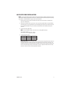
Voltage Red Wire Black Wire
12 VDC + Ground
24 VAC ~ ~