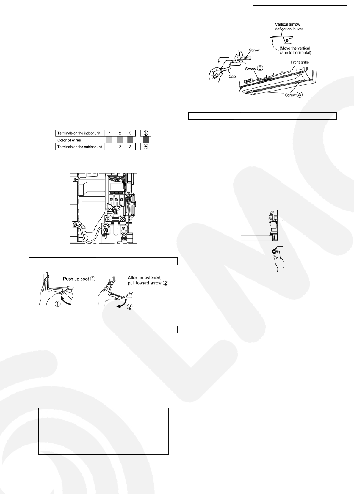
11.2.5. Connect The Cable To The Indoor
Unit
1. The inside and outside connecting cable can be connected
without removing the front grille.
2. Connecting cable between indoor unit and outdoor unit
shall be approved polychloroprene sheathed 4 × 1.5 mm
2
flexible cord, type designation 245 IEC 57 (H05RN-F) or
heavier cord.
•
• •
•
Ensure the color of wires of outdoor unit and the
terminal Nos. are the same to the indoor’s respectively.
•
• •
•
Earth lead wire shall be longer than the other lead wires
as shown in the figure for the electrical safety in case of
the slipping out of the cord from the anchorage.
•
• •
•
Secure the cable onto the control board with the holder
(clamper).
HOW TO TAKE OUT CORNER PIECE (LEFT UNDER)
HOW TO TAKE OUT FRONT GRILLE
Please follow the steps below to take out front grille if
necessary such as when servicing.
1. Set the vertical airflow direction louver to the horizontal
position.
2. Slide down the two caps on the front grille as shown in the
illustration at the right, and then remove the three mounting
screws.
3. Pull the lower section of the front grille towards you to
remove the front grille.
Caution
When reinstalling the front grille, first set the vertical
airflow direction louver to the horizontal position and
then carry out above steps 2 - 3 in the reverse order.
Please check that the top side of front grille certainly
caught with fixative rib (4 points) of indoor unit.
AUTO SWITCH OPERATION
The below operations will be performed by pressing the
“AUTO” switch.
•
• •
•
AUTO OPERATION MODE
The Auto operation will be activated immediately once the
Auto Switch is pressed.
•
• •
•
TEST RUN OPERATION (for PUMP DOWN/SERVICING
PURPOSE)
The Test Run operation will be activated if the Auto Switch
is pressed continuously for more than 5 sec. to below 8 sec.
A “pep” sound will occur at the fifth sec., in order to identify
the starting of Test Run operation.
51
CS-HE9DKE CU-HE9DKE / CS-HE12DKE CU-HE12DKE


