


Installer Manual
7
INSTALLATION
Before You Begin
Be sure the actual work is performed by experienced personnel, licensed to carry out
security system installations and capable of implementing all applicable requirements of the
National Fire Protection Association (NFPA-70 and NFPA-74), as well as any federal, state,
and local codes–along with any safety guidelines and regulations which might apply.
Mounting and Wiring the Control Panel (refer to figures 1A, 1B & 1C on pages
32, 33 & 34)
1. Mount the ORBIT-6’s metal cabinet at a protected dry location, near a source of
unswitched AC Power, a good ground, and access to telephone service. Use the proper
hardware (e.g. anchors, mollys, toggle bolts, etc.), as required, to insure a suitable
mounting.
2. Thread all electrical wiring through a convenient hole in the metal cabinet. To prevent
potential damage, be sure that live AC power is NOT present and that the Standby
Battery is NOT connected. Refer to Figures 1A and 1B. Your wiring may include any
and all of the following:
• connections to Hardwired Zones
• connections to devices requiring Uninterrupted Auxiliary Power (e.g. PIRs, Glass
Break Detectors)
• connections to Smoke Detectors requiring Resettable Power
• connections to any External Sounders
3. If using Utility Output, connect the UO/ECL output, this terminal is designed to activate a
low current device (e.g. a 12 VDC Relay, drawing no more than 70 mA).
If using UO expansion module, connect the UO/ECL terminal to the ECL terminal input
in the expansion module. In this case the first UO on the expansion module will become
UO1. (see figures A1)
4. Make connections from the RJ31X (or equivalent) telephone company interface.
5. Make connections to the system’s keypad(s) by the correspnding wire colors.
6. Make connections to AC Power (via a 16.5 VAC, 25 VA transformer). Do not plug in the
transformer at this time.
7. Have a Standby Battery ready (typically 12 VDC, 4 AH), but do not connect it at this
time.
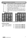
8. All zone inputs are End Of Line supervised, use 2200 ohm resistors (supplied).
9. When using 8 LED keypad, zones 7 & 8 are end-of-line supervised. Use 2200 ohm
resisters (supplied) when the zones are not in use. For further wiring instructions of the
8 LED keypad, refer to Figure 1C on page 34.
10. If using a Key-switch, use a momentary key-switch. The receiver (if used) must give a
pulse output and not on/off.
11. To connect the panic button use the white wire as (+) and the black wire as (-).
Note: The maximum distance between the panic button and the keypad is 30 meters.