


26
2. The thermostat wires (R, W, Y, and G) are
securely connected to the correct leads on
the terminal strip of the circuit board.
3. The gas line service pressure does not
exceed 10.0 in. water column (0.36 psig),
and is not less than 4.5 in. water column
(0.16 psig) for natural gas. For LP gas the
line service pressure must not exceed 14 in.
water column (0.51 psig), and must not be
less than 11.0 in. W.C. (0.40 psig).
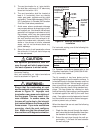
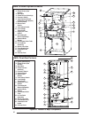
4. The roll-out and vent safety manual reset
switches are closed. If necessary, press the
red button to reset a switch. See Figure 28
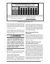
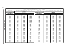
* Time-delay fuses or HACR-type circuit breakers are required.
Table 11. Electrical Data
for location. DO NOT install a jumper wire
across a switch to defeat its function. If a
switch reopens on start-up, DO NOT reset
the switch without identifying and correct-
ing the fault condition which caused the
switch to trip.
5. The blower door is in place, closing the door
switch in the line voltage circuit.
6. The gas line has been purged and all con-
nections are leak tight.
Start-Up Procedure
1. Set the thermostat to the lowest setting.
2. Close the disconnect(s) to provide line volt-
age to the furnace.
3. Follow the procedures given on the operat-
ing instructions label attached to the furnace.
4. Set the thermostat above room tempera-
ture and verify the sequence of operation.
(See the SEQUENCE OF OPERATION.)
5. After the furnace has run for approximately
five minutes, set the thermostat below room
temperature and verify steps (9) through
(11) of the SEQUENCE OF OPERATION.
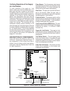
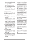
Verifying and Adjusting
Firing Rate
The firing rate must be verified for each installa-
tion to prevent over-firing the furnace.
NOTE: The firing rate must not exceed the rate
shown on the furnace rating plate. At altitudes
above 2000 ft. the firing rate must be adjusted as
described in the high altitude section.
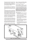
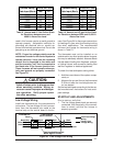
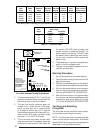
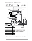
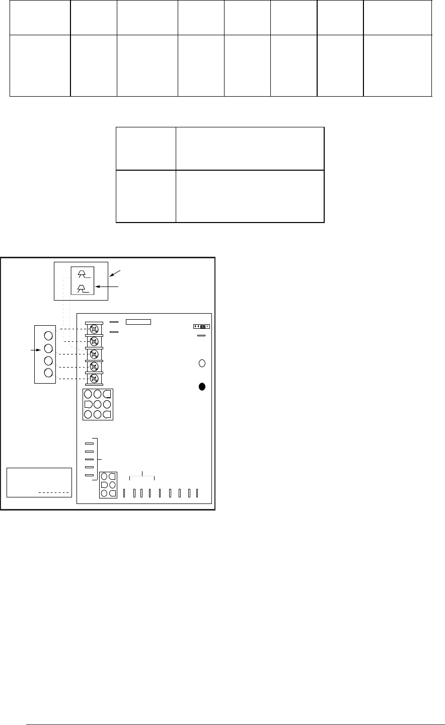
Figure 24. Low Voltage Field,
Four-wire Heating/Cooling Applications
R C Y G W
A/C Condensing Unit
Condensing Unit
Control Box
Room
Thermostat
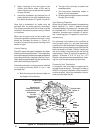
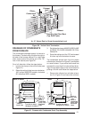
Flame Signal Light
(Yellow)
Status Light
(Red)
60
90
120
180
Blower Off
Timing
TWIN
3 Amp
Fuse
COM
24 V
HUM
Neutrals
Low Voltage
Connections
41
52
63
7
8
9
4
5
6
1
2
3
EAC
HUM
M1
M2
M3
COOL
HEAT
L1
XFMR
Unused Motor Leads
EAC
R Y G W
Connect
R & W
For
Heating
Only
FIELD WIRING
NOTE: The "Y"
terminal on the
UTEC control board
must be connected
to the thermostat.
Furnace Cabinet Nominal Maximum Minimum Maximum Minimum Maximum
Input Width Electrical Operating Operating Furnace Wire Fuse or Circuit
(Btuh) (in.) Supply Voltage Voltage Amperes Gauge Breaker Amps*
40,000 14.25 115-60-1 127 103 12.2 14 15
60,000 14.25 115-60-1 127 103 12.2 14 15
80,000 19.75 115-60-1 127 103 14.1 14 15
100,000 19.75 115-60-1 127 103 14.1 14 15
120,000 22.50 115-60-1 127 103 17.3 12 20
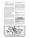
Thermostat Recommended Thermostat
Wire Wire Length
Gauge 2-wire 4 or 5-wire
(heating) (cooling)
24 55 ft. 25 ft.
22 90 ft. 45 ft.
20 140 ft. 70 ft.
18 225 ft. 110 ft.