


19
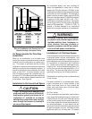
5. The vent termination for a 1-pipe installa-
tion shall be a minimum of 3 ft. above any
forced air inlet within 10 ft.
6. The vent termination shall be located at
least 4 ft. horizontally from any electric
meter, gas meter, regulator and any relief
equipment. These distances apply ONLY to
U.S. installations. In Canada, the Canadian
Fuel Gas Code takes precedence.
7. Avoid areas where condensate drainage
may cause problems by dropping on plant-
ers or patios, etc. Also ensure that exhaust
gases will not impinge on windows or build-
ing surfaces, which may be compromised
or damaged by condensation. Do not install
the vent terminal such that exhaust is di-
rected into window wells, stairwells, under
decks or into alcoves or similar recessed
areas, and do not terminate above any
public walkways.
8. Select the point of wall penetration where
the minimum 1/4 inch per foot of slope up
can be maintained.
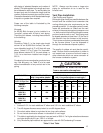
!
CAUTION:
For optimum performance, vent fur-
nace through wall which experiences
the least exposure to winter winds.
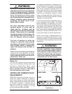
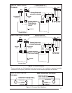
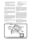
Horizontal Venting
Vent and combustion air intake terminations
must be as shown in Figure 19.
!
WARNING:
Ensure that the combustion air vent
and the exhaust vent are configured as
shown in Figure 19. Improper vent
termination can cause recirculation of
the flue gases. This may result in fur-
nace vibration. In severe cases, the
furnace will cycle due to the intermit-
tent contact between the flame and the
flame sensor. If you note oscillations
occurring, check the vent configura-
tion. Make sure that the exhaust vent
does not have a 90 degree termination.
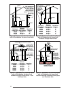
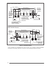
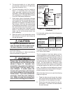
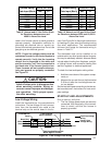
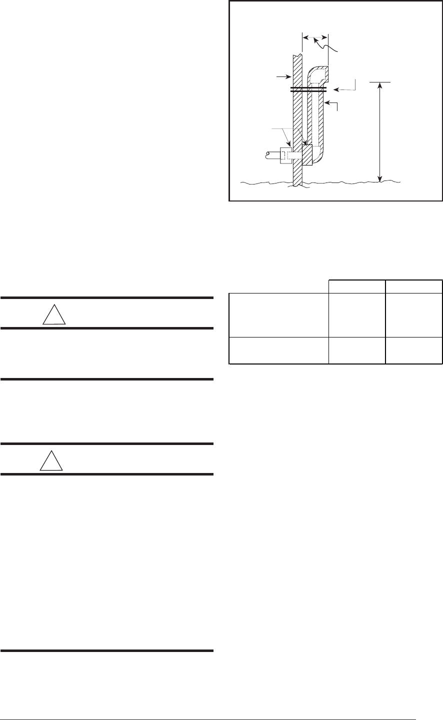
Figure 18. Alternate Horizontal Vent
Installation
Outside
Wall
Support
Pipe
Coupling
Vent Configuration to
Provide 12" Minimum
height above
Snow Level.
1/2"
Armaflex
Insulation or
Equivalent
12" Above
Normally
Expected
Snow
Level
12" Min.
19" Max.
For horizontal venting, one of the following kits
is recommended:
2" PVC 3" PVC
Through-the-Wall
Exterior Vent
Mountin
g
Kit
9023730 9023750
Neutralizer Kit - All
Models
9023730 9023730
For Canadian installations please refer to the
Canadian Installation Code (CAN/CGA-B149.1
or 2) and/or local codes.
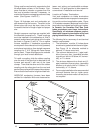
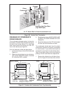
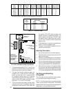
The kit consists of two face plates and an
insulating gasket to seal the exterior surface. A
hole sized closely to the pipe diameter must first
be cut through the wall. A short length of pipe is
then cut such that it can penetrate the wall and
be held in place by closely fitting standard cou-
plings. The face plates are retained on both
sides of the wall by the couplings, and the gasket
is retained against the wall by the outer face
plate. Face plates must be fastened to the wall
and the outside one must be flashed as appro-
priate to prevent entry of water.
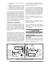
When the above kits are not used the following
steps are required:
1. Check the hole size cut through the exterior
wall. Insure that the hole diameter is less than
the diameter of the couplings to be used.
2. Extend the vent pipe through the wall ap-
proximately 1" and seal the area between
the wall and pipe.