


18
4 ft. min
12 in. min
12 in. min
12 in. min
9 in.
4 ft. min
12 in. min
12 in. min
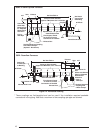
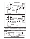
Mechanical
draft vent
terminal
Direct vent
terminal
50,000 Btuh
or less
Forced
Air Inlet
Direct vent
terminal -
more than
50,000 Btuh
Mechanical
draft vent
terminal
Mechanical
draft vent
terminal
Grade
Less
than 10 ft.
3 ft. min.
Piping must be mechanically supported so that
its weight does not bear on the furnace. Sup-
ports must be at intervals no greater than five
feet, and at smaller intervals if necessary to
ensure that there are no sagging sections to trap
water. (See Figures 14 and 15.)
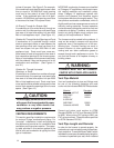
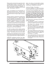
Figure 16 illustrates vent and combustion air
pipe sizes exiting the furnace. Transition to the
correct pipe size must be done close to the
furnace so that the full length of pipe is of proper
size.
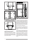
Straight neoprene couplings are supplied with
the downflow furnaces only. These couplings
are to be installed in the combustion air inlet (if
present) and exhaust vent piping at the furnace
as shown in Figures 13 and 14. For an upflow
furnace installation, if breakable connections
are required in the combustion air inlet (if present)
and exhaust vent piping, then straight neoprene
couplings for 2” or 3” piping with hose clamps
can be used. These couplings can be ordered
through your local furnace distributor.
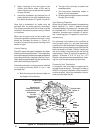
To install a coupling, slide the rubber coupling
over the end of the pipe that is attached to the
furnace and secure it with one of the hose
clamps. Then slide the other end of the rubber
coupling onto the other pipe from the vent and
secure the coupling with the second hose clamp.
Ensure that the connection is tight and leak free.
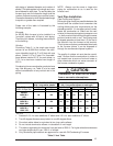
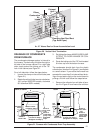
NORDYNE condensing furnaces have been
certified for installation with zero clearance be-
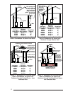
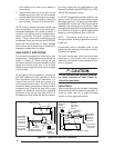
Figure 17. Vent Termination Clearances
tween vent piping and combustible surfaces.
However, it is good practice to allow space for
convenience in installation and service.
Location of Outdoor Terminations
Vent and combustion air intake terminations
must be located to ensure proper furnace opera-
tion and to conform to applicable codes. Figure
16 illustrates necessary distances from the vent
termination to windows and building air intakes.
In Canada, the Canadian Fuel Gas Code
takes precedence over these instructions.
Specifically, all minimum distance require-
ments with respect to termination of the vent
piping listed below (items 1 through 8).
The following list is a summary of vent terminal
location requirements:
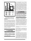
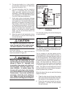
1. The termination must be 12 inches above
snow level or grade level whichever is higher.
See Figure 18 for alternate method to
achieve 12" above snow level.
2. The minimum distance for a (1-pipe instal-
lation) from any door, (openable) window,
or gravity air inlet is 4 ft. below, 4 ft. horizon-
tally, or 1 ft. above.
3. The minimum distance for a direct vent (2-
pipe) installation) from any door, (openable)
window, or air gravity inlet is 1 ft. below, 1 ft.
horizontally, or 1 ft. above.
4. For one-pipe installations the recommended
minimum distance from an inside corner
formed by two exterior walls is 6 feet, but is
not required.