


20
3. Apply couplings to the vent pipe on the
interior and exterior sides of the wall to
insure the pipe can not be pushed or pulled
through the wall.
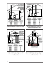
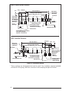
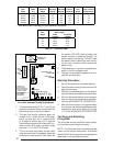
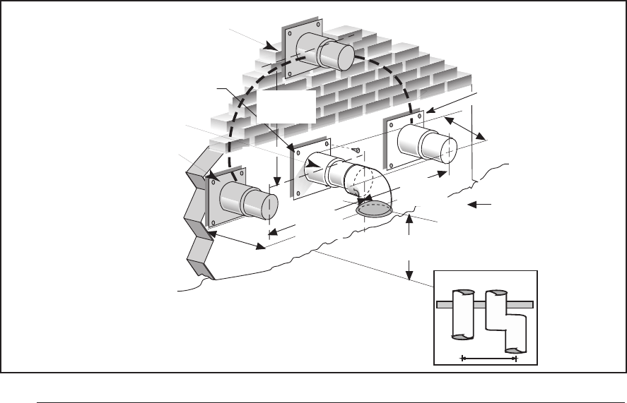
4. Insure the combustion air inlet pipe (for a 2
pipe installation) has a 90 degree termina-
tion elbow as shown in Figures 19 and 20.
Note that a combustion air intake must be
provided with an elbow opening downward.
The screen provided with the furnace must be
installed in the elbow to prevent entry of debris
or creatures.
When the vent pipe must exit an exterior wall
close to the grade or expected snow level, a riser
should be provided as shown in Figure 18.
Insulation is required to prevent freezing of this
section of pipe.
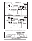
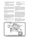
Vertical Venting
Figure 20 shows the proper installation and clear-
ances for vertical vent termination. The roof penetra-
tion must be properly flashed and waterproofed with
a plumbing roof boot or equivalent flashing. Termi-
nation spacing requirements from the roof and from
each other must be per Figure 20.
Vent and combustion air piping may be installed
in an existing chimney which is not in use
provided that:
a. Both the exhaust vent and air intake run
the length of the chimney.
b. The top of the chimney is sealed and
weatherproofed.
c. The termination clearances shown in
Figure 20 are maintained.
d. No other gas fired appliances are vented
through the chimney.
Vent Freezing Protection
When the vent pipe is exposed to temperatures
below freezing, i.e., when it passes through
unheated spaces, chimneys, etc., the pipe must
be insulated with 1/2 inch thick sponge rubber
insulation, Armaflex-type insulation or equiva-
lent. Insulating pipe is important to avoid con-
densate icing.
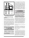
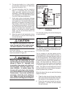
For extremely cold climates or for conditions of
short furnace cycles (i.e. set back thermostat
conditions) the last three feet of vent pipe can be
reduced one nominal pipe size provided that the
total vent length is at least 15 feet in length and
the vent is sized in accordance with the venting
requirements (Table 5) before this reduction is
applied. (Example: 3" to 2-1/2" or 2" to 1-1/2")
Smaller vent pipes are less susceptible to freez-
ing, but must not be excessively restrictive.
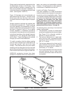
Concentric Vent Termination
A concentric vent termination is approved for
use with these furnaces. The kit part number is
903578. For proper installation of the concentric
vent termination, follow the installation instruc-
tions provided with that kit.
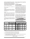
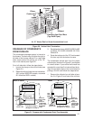
36" max.
18" min.
Exhaust Vent
Option B
Exhaust Vent
Option A
Exhaust Vent
Option C
Mounting Kit
Faceplate Secured
to Wall with Screws
18" Min.
36" Max.
7" Min.
8" Min.
12" Min. to
Normal Snow Level
Combustion
Air Inlet
Grade
Level
or Normal
Snow
Inlet
Exhaust
18" Min.
36" Max.
Figure 19. Exhaust and Combustion Air Pipe Clearances