


25
used in this furnace require an earth ground to
operate properly. Acceptable methods for
grounding are electrical wire or conduit ap-
proved for electrical ground service. Do not use
gas piping as an electrical ground.
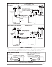
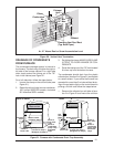
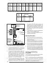
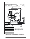
NOTE: Proper line voltage polarity must be
maintained in order for the control system to
operate correctly. Verify that the incoming
neutral line is connected to the white wire
and the incoming "hot" line is connected to
the black wire in the furnace junction box.
These furnaces will not operate unless po-
larity and ground are properly connected.
See Figure 23.
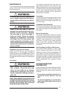
!
CAUTION:
Label all wires prior to disconnection
when servicing controls. Wiring er-
rors can cause improper and danger-
ous operation. Verify proper opera-
tion after servicing.
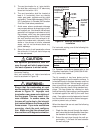
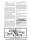
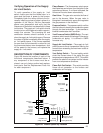
Low Voltage Wiring
Install the thermostat per the manufacturer's
instructions. The low voltage (24 volt) connec-
tions from the thermostat are made at the
terminal strip on the control board in the fur-
nace. See Figure 24 for the proper connections
for heating only (two-wire) and heating/cooling
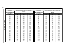
(four-wire) applications. The recommended
minimum wire gauge for thermostat wiring is
shown in Table 11.
The thermostat must not be installed on an
outside wall or any other location where its opera-
tion may be adversely affected. Adverse affects
include radiant loading from fireplaces, sunlight,
or lighting fixtures, and convective loading from
warm air registers or electrical appliances.
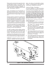
To check the heat anticipator setting either:
1. Add the current draw of the system compo-
nents; or
2. Measure the current flow on the thermostat
R-W circuit after the circulating blower mo-
tor has started.
Set the heat anticipator according to the thermo-
stat manufacturer's instructions for heat antici-
pator settings.
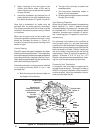
START-UP AND ADJUSTMENTS
Prior to start-up, verify that:
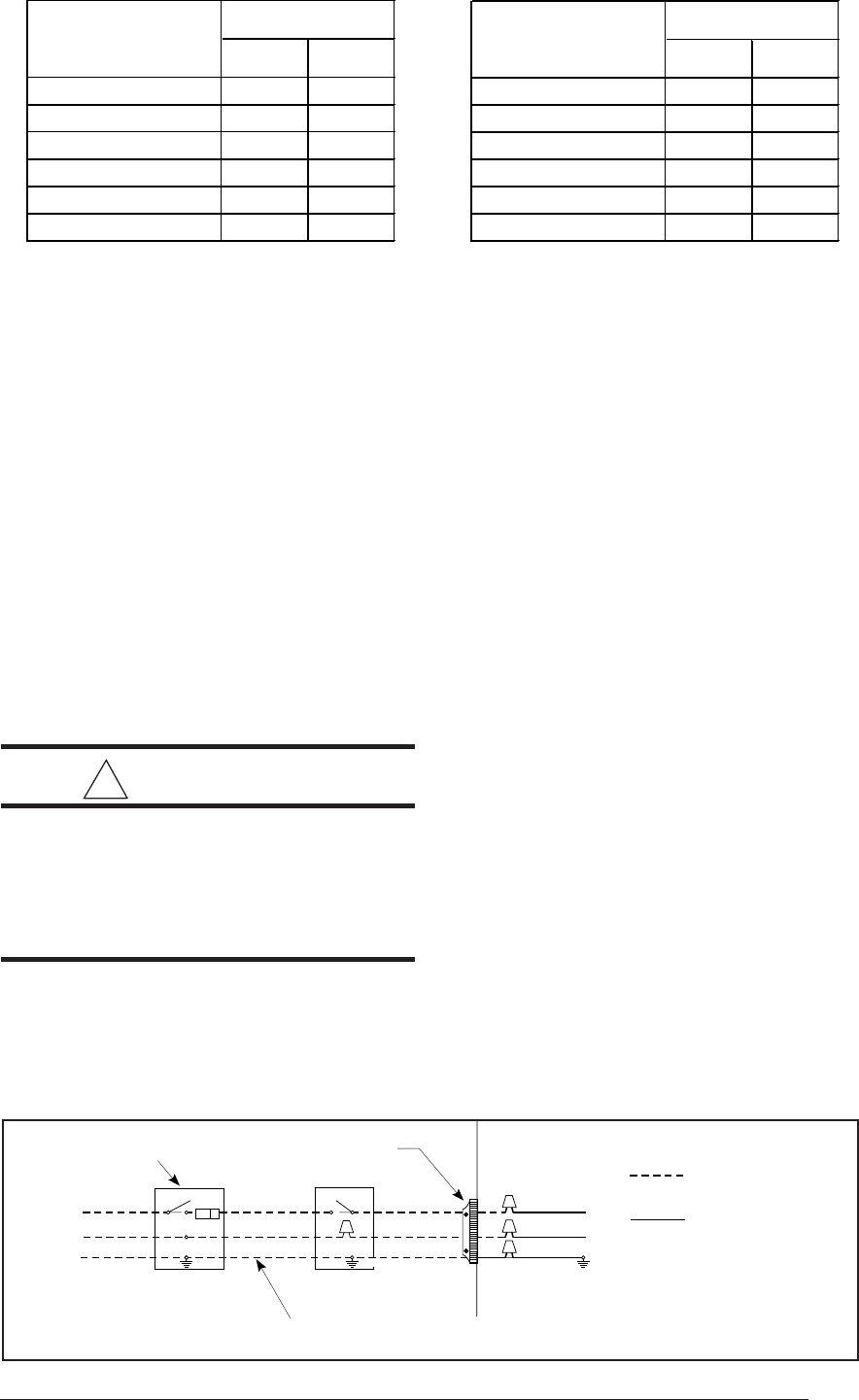
1. The line voltage power leads are securely
connected, that the polarity of the connec-
tions is correct, and that the furnace is
properly grounded.
Field Supplied Disconnect
Within Sight of Furnace
Field Supplied
Panel Connector
Field Supplied
Fused Service
Panel
Black (Hot)
White (Neutral)
Green or Bare
(Ground)
Black
White
Black
White
Black
White
Field Line Voltage
Wiring
Factory Line
Voltage Wiring
Ground
Ground
Ground
Figure 23. Line Voltage Field Wiring
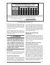
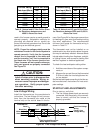
Table 9. Natural and LP Gas Orifice Sizes
for Elevations between zero and
4999 ft. Above Sea Level
Furnace Rating
Plate Input (Btu/h)
Nat LP
45000 44 54
60000 45 55
72000 43 54
96000 43 54
120000 43 54
144000 43 54
Orifice Drill Size
Furnace Ratin
g
Plate Input (Btu/h)
Nat LP
45000 44 55
60000 45 56
72000 43 55
96000 43 55
120000 43 55
144000 43 55
Orifice Drill Size
Table 10. Natural and LP gas Orifice Sizes
for Elevations between 5000 and 10,000 ft.
Above Sea Level