


21
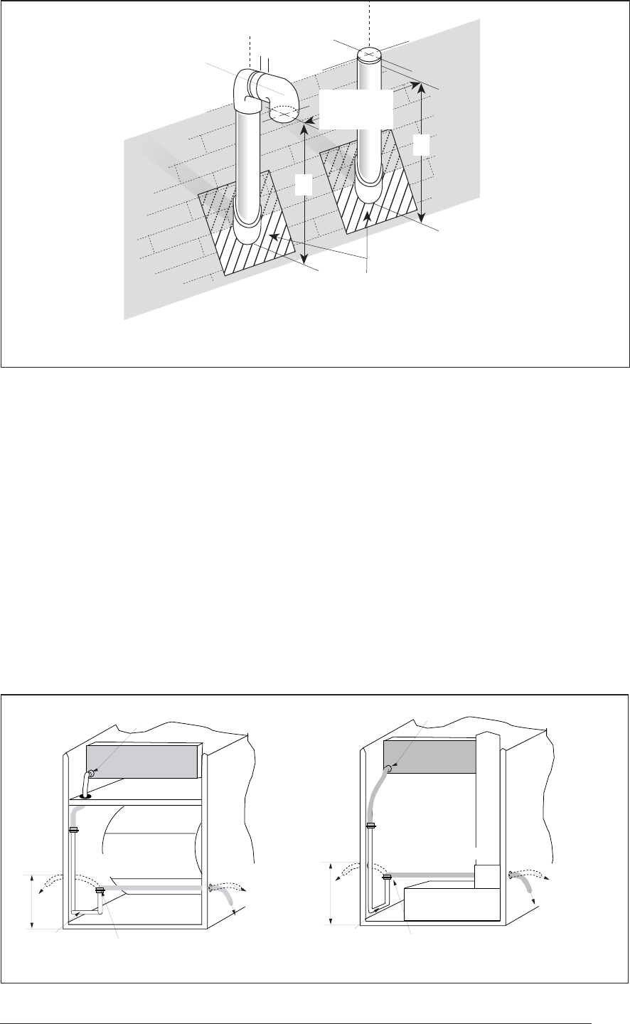
Combustion
Air
Intake
Elbow
Exhaust
Vent
Exhaust
Plumbing Vent Roof Boot
(Typ. Both Pipes)
A
1"
18" Min.
36" Max.
A
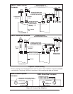
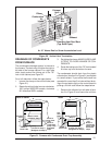
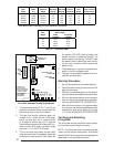
Figure 20. Vertical Vent Termination
A= 12" Above Roof or Snow Accumulation Level
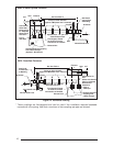
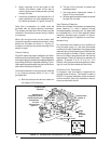
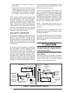
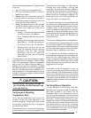
DRAINAGE OF CONDENSATE
FROM FURNACE
The condensate drainage system is internal to
the furnace. The drain may exit either the right or
left side of the furnace cabinet. For a right side
drain simply extend the tubing out of the 7/8"
hole in the cabinet, see Figure 21.
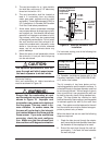
For a left side drain follow the steps below:
1. Loosen the clamp on the soft exit tube (see
Figure 21.)
2. Rotate the soft exit tube (counter clockwise,
180° upflow G6RC/RD models; clockwise
90° downflow G6RL models.)
8"
Left Side
Drain
"HARD" J
Drain Tube
Clamp
(Loosen For Step 1)
(Retighten for Step 3)
Route to
floor drain.
...OR
Route to
condensate
pump. Keep
downward
slope.
Collector Box
A
Rotate counter
clockwise (Step 2)
8"
Left
Side
Drain
"HARD" J
Drain Tube
Clamp
(Loosen For Step 1)
(Retighten for Step 3)
Route to
floor drain.
...OR
Route to
condensate
pump. Keep
downward
slope.
Collector Box
A
Rotate clockwise
(Step 2)
G6RLG6RC & G6RD
3. Re-tighten the clamp. MAKE SURE CLAMP
IS TIGHT TO AVOID LEAKAGE OF CON-
DENSATE.
4. Route the tubing out of the 7/8" hole located
8 inches up from the bottom furnace.
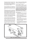
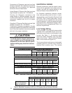
The condensate should drain from the plastic
collector box (location A in Figure 21) as droplets
or a small stream. If you notice the furnace has
operated for more than 5 minutes without drain-
ing or the red status light on the control board is
pulsing a 2-blink code follow the steps below.
1. Remove the collector box soft tube at loca-
tion A in Figure 21 and insure the exit from
Figure 21. Furnace with Condensate Drain Trap Assembly