


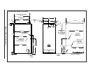
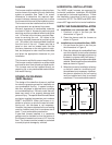
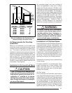
10
19.63"
18.75"
19.63"
13.25"
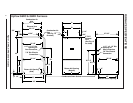
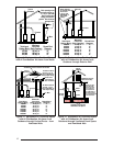
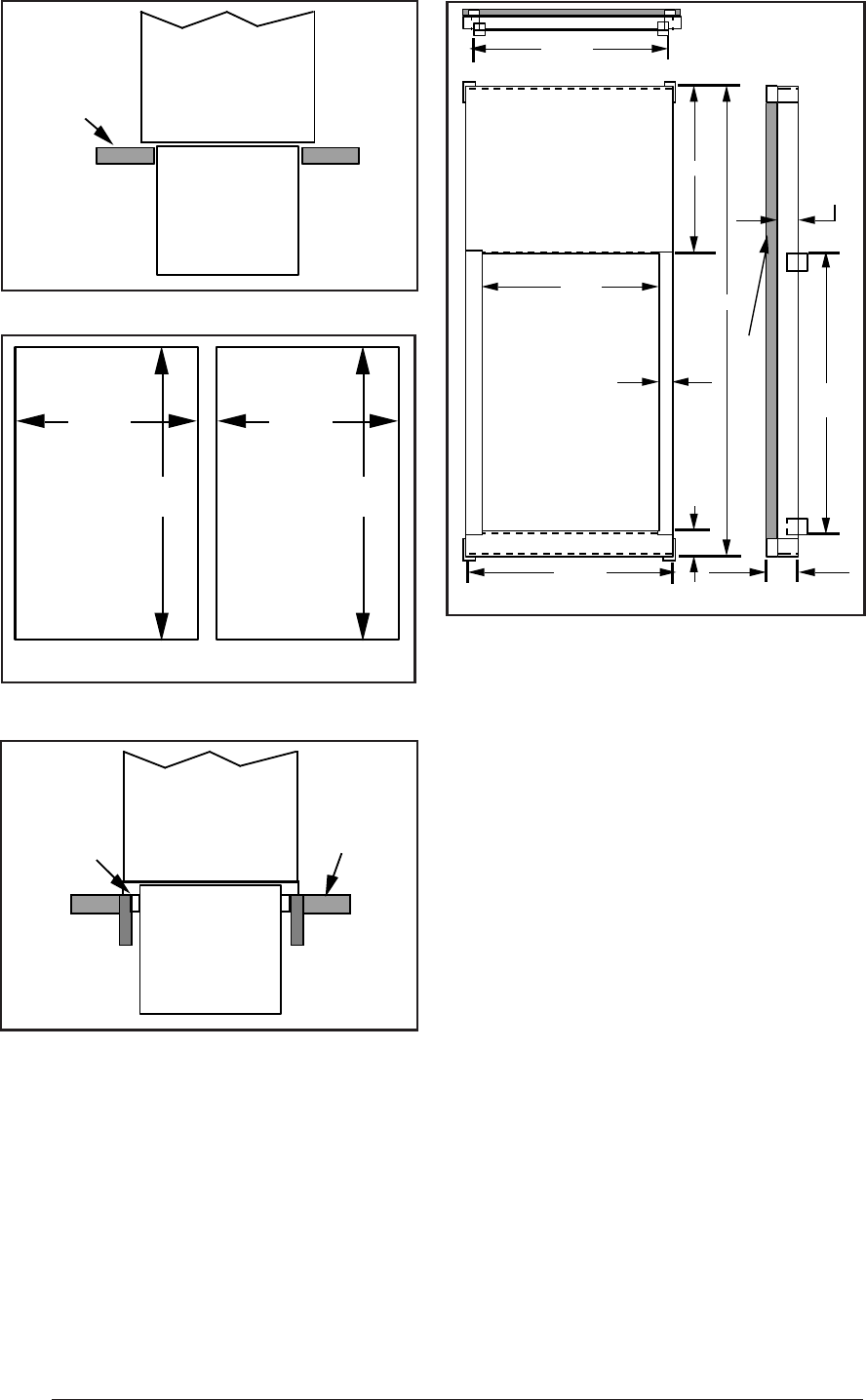
Hole in
Floor
Hole in
Floor
Downflow
Wood
Sub-base
Floor
Furnace
Sheet
Metal
Plenum
Figure 5. Opening in Wood Floor
G6RL 080/100 G6RL 040/060
Figure 6. Furnace on a Wood Floor
1 inch thick fiberglass 3 lb density
28.38"
9.25"
19.63"
3"
19.75"
or 14.25"*
2.0"
1.58"
1.50"
16.75"
or 11.25"*
18.75"
or 13.25"*
Concrete
Floor
Furnace
Sheet
Metal
Plenum
Figure 4. Furnace on a Concrete Slab
CIRCULATING AIR SUPPLY
Plenums and air ducts must be installed in
accordance with the Standard for the Installa-
tion of Air Conditioning and Ventilating Systems
(NFPA No. 90A) or the Standard for the Installa-
tion of Warm Air Heating and Air Conditioning
Systems (NFPA No. 90B).
* Smaller
dimensions for
G6RL 040/060
Figure 7. Downflow Sub-Base Dimensions
If outside air is utilized as return air to the furnace
for ventilation or to improve indoor air quality, the
system must be designed so that the return air to
the furnace is not less than 50°F (10°C) during
heating operation. If a combination of indoor and
outdoor air is used, the ducts and damper system
must be designed so that the return air supply to
the furnace is equal to the return air supply under
normal, indoor return air applications.
When a cooling system is installed which uses
the furnace blower to provide airflow over the
indoor coil, the coil must be installed down-
stream (on the outlet side) or in parallel with the
furnace.
If a cooling system is installed in parallel with the
furnace, a damper must be installed to prevent
chilled air from entering the furnace and con-
densing on the heat exchanger. If a manually
operated damper is installed, it must be de-
signed so that operation of the furnace is pre-
vented when the damper is in the cooling posi-
tion and operation of the cooling system is
prevented when the damper is in the heating
position.