


22
Leak Check
After the gas piping to the furnace is complete,
all connections must be tested for gas leaks. To
check for leaks use only a soap and water
solution or other approved method.
Some Utilities
Require Shut-
Off Valve to
be 4 to 5 feet
Above Floor
Denotes field-
provided and
installed
components.
Shut-Off Valve
with
1/
8" NPT
Plugged Tap
Burner Viewport
Roll-Out Limit
Automatic Gas Valve
(with manual shut-off)
Burner
Assembly
Ground
Joint
Union
the collector box is clear of any debris or
obstructions.
2. Replace this tube and insure the fit to the
header spout is air tight. Air will be drawn
into the header if this connection is not tight.
3. Check other tube connections along the
drain system. Insure that all are air tight.
NOTE: Industry research studies indicate that
when condensate is routed to an active drain,
household detergents, etc., buffer its acidity. If
the drain is not actively used or if codes require,
obtain a neutralizer kit (usually contains lime-
stone). Proper drains and connections to the
condensate tubing are required as NORDYNE
cannot be held responsible for water leakage
which occurs due to loose hose connections or
improperly sealed drain line pipes.
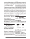
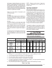
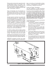
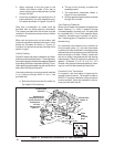
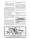
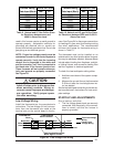
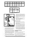
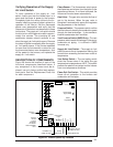
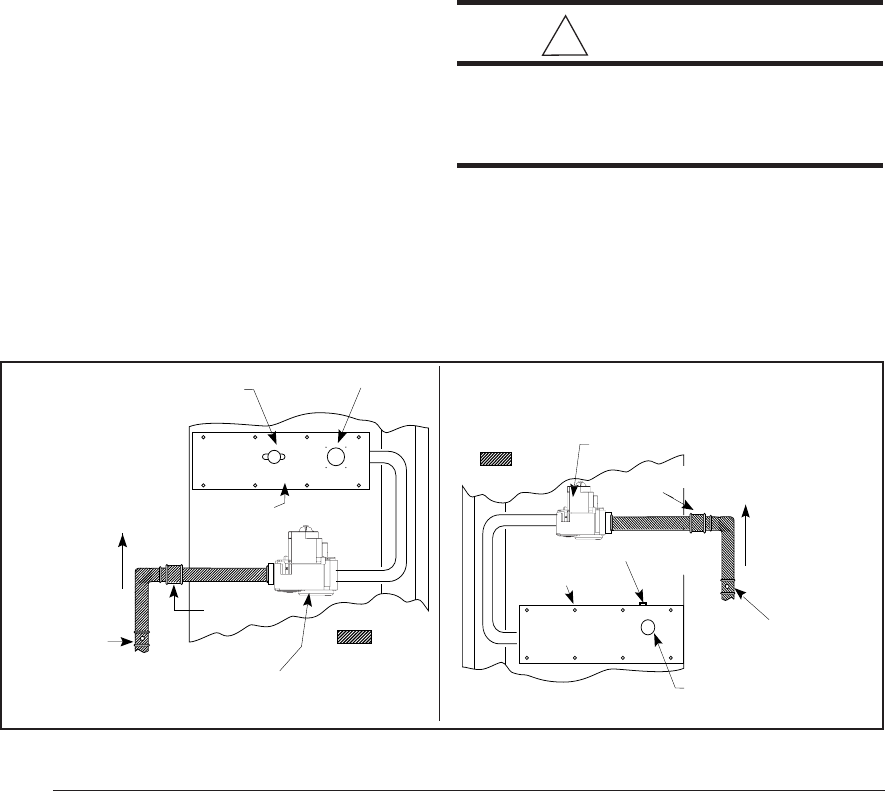
GAS SUPPLY AND PIPING
This furnace is equipped for either left or right
side gas entry. Typical gas service hook-ups are
shown in Figure 22. When making the gas
connection provide clearance between the gas
supply line and the entry hole in the furnace
casing to avoid unwanted noise and/or damage
to the furnace.
All gas piping must be installed in compliance
with local codes and utility regulations. Some
local regulations require the installation of a
manual main shut-off valve and ground joint
union external to the furnace. The shut-off valve
should be readily accessible for service and/or
emergency use. Consult the local utility or gas
supplier for additional requirements regarding
placement of the manual main gas shut-off. In
the absence of local codes the gas line installa-
Figure 22. Typical Gas Service Connection
Some Utilities
Require Shut-
Off Valve to
be 4 to 5 feet
Above Floor
Denotes field-
provided and
installed
components.
Shut-Off Valve
with
1/
8" NPT
Plugged Tap
Burner Viewport
Automatic
Gas Valve
(with manual
shut-off)
Burner
Assembly
Ground Joint
Union
Roll-Out Limit
tion must comply with the latest edition of the
National Fuel Gas Code (ANSI Z223.1) or (CAN/
CGA B149) installation codes.
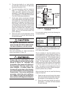
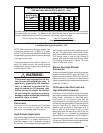
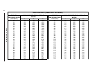
A 1/8" NPT plugged tap must be installed in the
gas line to the unit for use when measuring the
gas supply pressure. The plug should be readily
accessible for service use. A drip leg should be
installed in the vertical pipe run to the unit. Table
5 lists gas flow capacities for standard pipe sizes
as a function of length in typical applications
based on nominal pressure drop in the line.
NOTE: Gas piping must not be run in or
through air ducts, chimneys, gas vents, elevator
shafts, etc.
Compounds used on threaded joints of gas
piping must be resistant to the actions of lique-
fied petroleum gases.
The main manual gas valve and main power
disconnect to the furnace must be properly
labeled by the installer in case emergency shut-
down is required.
!
CAUTION:
Do not use matches, lighters, candles,
or other sources of open flame to
check for gas leaks.