


5
W415-0612 / C / 01.25.08
33
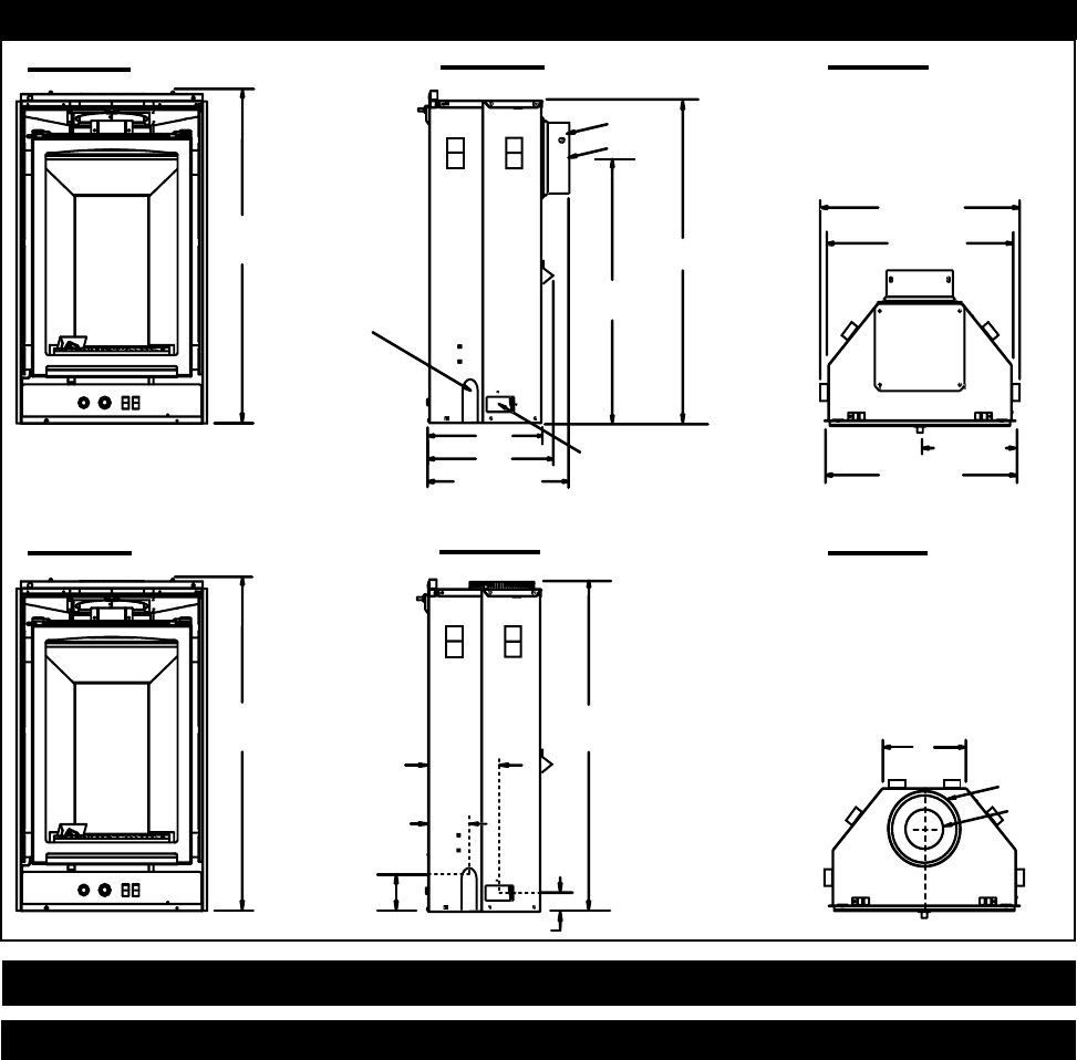
1
/
8
”
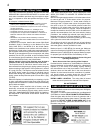
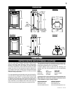
4” DIA.
7” DIA.
13”
15
3
/
8
”
12”
26
3
/
8
”
34
1
/
8
”
34
1
/8”
33
7
/
8
”
9
1
/
2
”
5”
2
1
/
2
”
1
3
/
4
”
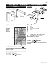
GAS
LINE
ACCESS
ELECTRICAL
ACCESS
4” DIA.
7” DIA.
10
1
/
4
”
20
1
/
2
”
19
3
/
4
”
21
3
/
4
”
9”
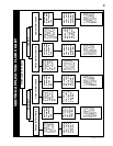
DIMENSIONS
FIGURE 1a
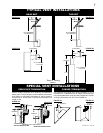
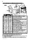
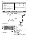
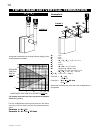
VENTING
VENTING LENGTHS AND AIR TERMINAL LOCATIONS
Use only Wolf Steel, Simpson Dura-Vent, Selkirk Direct
Temp or American Metal Amerivent venting components.
Minimum and maximum vent lengths, for both horizontal
and vertical installations, and air terminal locations for either
system are set out in this manual and must be adhered to.
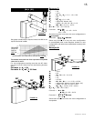
For Simpson Dura-Vent, Selkirk Direct Temp and American
Metal Amerivent, follow the installation procedure provided
with the venting components.
For vent systems that provide seals on the inner exhaust fl ue,
only the outer air intake joints must be sealed using red high
temperature silicone (RTV). this same sleant may be used
on both the inner exhaust and outer intake vent pipe joints of
all other approved vent systems except for the exhaust vent
pipe connection to the fi replace fl ue collar which must be
sealed using the black high temperature sealant Mill Pac.
The connection between the adaptor for these systems and
the fi replace fl ue collar must be sealed using the black high
temperature sealant Mill Pac (not supplied).
A starter adaptor must be used with the following vent
systems and may be purchased from the corresponding
supplier:
PART 4"/7" SUPPLIER
Duravent W175-0053 Wolf Steel
Amerivent 4DSC-N2 American Metal
Direct Temp 4DT-AAN Selkirk
For Simpson Dura-Vent, Selkirk Direct Temp and American
Metal Amerivent, follow the installation procedure found
on the website for your venting supplier:
VENTING SUPPLIER WEBSITE ADDRESS
Simpson Dura-Vent www.duravent.com
Selkirk Direct Temp www.selkirkcorp.com
American Metal Amerivent www.americanmetalproducts.com
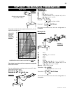
FIGURE 1b
FIGURE 1c
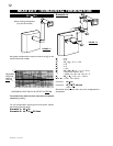
FIGURE 1d
FIGURE 1e
FIGURE 1f