


18
W415-0612 / C / 01.25.08
Use only approved fl exible vent pipe kits marked:
“Wolf Steel Approved Venting” as
identifi ed by the stamp only on the
7” fl exible vent pipe.
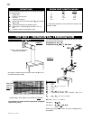
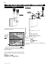
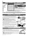
FIGURE 24
USING FLEXIBLE VENT COMPONENTS
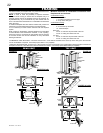
FIGURES 22a&b
Six inches (6") is the minimum bend radius allowed for
the seven inch (7") diameter fl exible vent pipe.
For optimum performance it is recommended that all
horizontal runs have a minimum 1" rise per foot using
fl exible vent components.
ELBOW
SPACERS
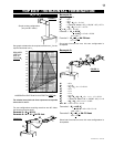
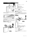
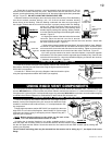
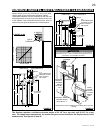
1. Fasten the roof support to the roof using the screws provided. The roof support is optional. In this case the venting is to
be adequately supported using either an alternate method suitable to the authority having
jurisdiction or the optional roof support. Figure 25.
2. Stretch the 4" fl exible vent pipe to the required length. Slip the 4" fl exible vent pipe
a minimum of 2” over the inner sleeve of the air terminal connector and secure with 3 #8
screws. Seal using a heavy bead of high temperature sealant W573-0007 (not supplied).
Figure 26.
NOTE: If using pipe clamps to connect vent components, 3 screws must also
be used to ensure the connection cannot slip off.
3. Repeat using the 7" fl exible vent pipe, using a heavy bead of high temperature
sealant W573-0002 (not supplied). Figure 26.
ROOF SUPPORT
FIGURE 25
VERTICAL AIR TERMINAL INSTALLATION
7” FLEXIBLE
VENT PIPE
7” COUPLER
4”
FLEXIBLE
VENT PIPE
#8 X 1/2”
SELF DRILLING
SCREWS AND
WASHERS
4” COUPLER
HIGH
TEMPERATURE
SEALANT
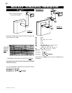
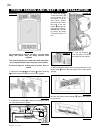
7” FLEXIBLE
VENT PIPE
SCREWS
#10x2"
VENT PIPE
2" OVERLAP
7" FLEXIBLE
4" FLEXIBLE
VENT PIPE
CAULKING
ATTENTI
ON-
CHAUD
CAUT
ION - HOT
HIGH TEMPERATURE
SEALANT
FIGURE 23
1. Stretch the 4" fl exible vent pipe to the required length taking into
account the additional length needed for the fi nished wall surface. Slip
the vent pipe a minimum of 2" over the inner sleeve of the air terminal
and secure with 3 #8 screws. Apply a heavy bead of the high temperature
sealant W573-0007 (not supplied).
NOTE: If using pipe clamps to connect vent components, 3 screws
must also be used to ensure the connection cannot slip off.
2. Using the 7" fl exible vent pipe, slide over the outer combustion air
sleeve of the air terminal and secure with 3 #8 screws. Seal using high
temperature sealant W573-0002 (not supplied).
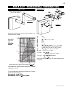
3. Insert the vent pipes through the fi restop maintaining the required
clearance to combustibles. Holding the air terminal (lettering in an upright,
readable position), secure to the exterior wall and make weather tight by
sealing with caulking (not supplied).
4. If more vent pipe needs to be used to reach the fi replace, couple them
together as illustrated. The vent system must be supported approximately
every 3 feet for both vertical and horizontal runs. Use noncombustible
strapping to maintain the minimum 1" clearance to combustibles.
The air terminal mounting plate may be recessed into the exterior wall
or siding by 1½", the depth of the return fl ange.
HORIZONTAL AIR TERMINAL INSTALLATION
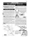
For safe and proper operation of the fi replace, follow the venting instructions exactly.
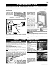
Do not allow the 4" flexible vent pipe
to bunch up on horizontal or vertical
runs and elbows. Keep it pulled
tight. A 1 1/4” air gap between the 4"
and 7" flexible vent pipes all around
is required for safe operation. A
spacer is required at the start, middle
and end of each elbow to ensure this
gap is maintained. Spacers are
attached to the 4" flexible vent pipe
at predetermined intervals to
maintain a 1-1/4” air gap to the 7"
flexible vent pipe. These spacers
must not be removed.
!
WARNING
For safe and proper operation of the fi replace, follow the venting instructions exactly.
All 4" fl exible vent pipe and 7" fl exible vent pipe joints may be sealed using high temperature sealant W573-0002
(not supplied) or the high temperature sealant W573-0002 Mill Pac (not supplied). However, the high temperature
sealant W573-0007 Mill Pac (not supplied) must be used on the joint connecting the 4" fl exible vent and the exhaust
fl ue collar.