


25
W415-0612 / C / 01.25.08
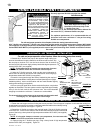
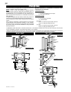
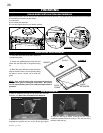
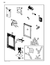
FIGURE 54
4. Place the thermal disk
assembly onto the stud
located at the lower left
of the fi rebox and behind
the support bracket.
5. Connect the wiring
for the variable speed
switch.
6. Insert the blower
assembly into the left
side under the firebox,
slide into the clip and
place onto the same stud
used for the thermal disk
assembly. Secure with
the lock washer and wing
nut supplied. Ensure that
the blower does not touch
the base of the fi rebox, any wiring or
controls. Ensure that the thermodisc is
touching the wall of the fi rebox.
HINT: Rest the thermal disk assembly forward against the
support bracket.
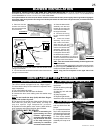
7. Place the variable speed switch into position and secure with
the pal nut supplied. (FIGURE 25) Reinstall the control panel and
install the variable speed switch knob.
NOTE: Plug into the receptacle on the right side of the
unit.
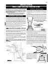
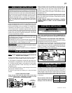
FIGURE 52
1. Remove the two
screws that secure
the control panel to the
front of the unit.
BLOWER INSTALLATION
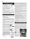
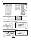
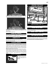
NIGHT LIGHT™ REPLACEMENT
1. Remove the door from
the fi rebox.
2. Run the wires up through
the lens hole.
3. Align key hole with lens
assembly.
4. Snap into place.
5. Replace light shields,
attach the wires and replace the door to the fi rebox.
LENS ASSEMBLY INSTALLATION
1. Remove the front door
and top shield from the
fi rebox.
2. Compress the retainer
fi ns in with a screw driver
while pressing fi rmly on the
top of the light assembly.
3. Once all the retainer
fi ns are pushed in the lens
assembly will snap out of
place.
LENS ASSEMBLY REPLACEMENT
ELECTRICAL INSTALLATION TO BE DONE BY A QUALIFIED INSTALLER and must be connected and grounded in
accordance with local codes. In the absence of local codes, use the current CSA C22.1 CANADIAN ELECTRICAL CODE in Canada or the
current ANSI/NFPA 70 NATIONAL ELECTRICAL CODE in the United States.
If an optional blower is to be used, the blower must be connected to the main power supply. Route a grounded 14 gauge 2-
wire power cable to the junction box and ground. At the point where the cable enters the junction box, a conduit connector
must be provided.
The GD19 comes equipped with our “Night Light™”.
If in the event the lamp or lens needs to be replaced, follow
these instructions.
1. Turn off all electrical supply.
2. Remove the front and door from the fi rebox.
3. Unscrew the lens cover making sure the washer stays
in place.
Note: Do not handle the lamp (bulb) with bare fi ngers,
protect with a clean dry cloth.
4. The lamp will pull straight out of the socket. Replace with
Wolf Steel Ltd. parts only (W387-0006), as lamp and
lens are special "high temperature" products.
5. Replace lens with gasket, lense covers, attach wires to
quick connects and replace the door when fi nished.
THE FIREBOX MUST BE SEALED.
When re-assembling the
light assembly, care must
be taken. “Light Leakage”
from above the cast doors
may be noticed. The holes
in the lamp housing are
necessary for ventilation
and must not be covered.
BULB REPLACEMENT
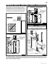
FIGURE 55
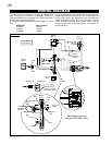
FIGURE 57
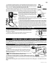
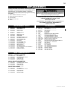
RED
BLACK
THERMAL DISK
VARIABLE SPEED SWITCH
BLOWER
WIRE
HARNESS
(included in GS66 kit)
WHITE
TO
POWER
SUPPLY
WHITE
GS66 WIRING DIAGRAM
VARIABLE
SPEED SWITCH
KNOB
2. Connect the black and red wires of the wire harness to the
prongs on the blower.
3. Connect the white and black wires of the wire harness to the
prongs on the thermodisc.
KEY HOLE
FIGURE 56
FIGURE 53