


30
W415-0612 / C / 01.25.08
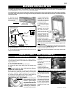
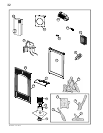
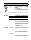
FIGURE 65
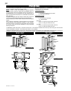
1. Turn off the electrical
and gas supply to the
fi replace.
2. Remove the front, glass
viewing door and log set.
3. Remove the 2 securing
screws. Slide the burner
assembly to the right and
lift out.
4. Using a deep
9
/
16
”
socket wrench, remove
the main burner orifi ce.
A
7
/
8
” back-up wrench
must be used on the
manifold, located below
the housing to ensure that
the aluminum tubing does
not twist or kink. Replace
the correct burner orifi ce
using pipe thread compound.
5. Loosen nut and replace with
appropriate pilot injector
6. Reinstall the burner ensuring that
the Venturi tube fi ts over the orifi ce.
NOTE: Check and adjust, if necessary, the primary air
to
1
/
16
” for propane and
1
/
32
" for natural gas. Replace the
screws.
7. Turn on the gas supply and check for gas leaks by brushing
on a soap and water solution.
Do not use open fl ame.
8. Replace the log set. Then light the pilot and main burner
to ensure that the gas lines have been purged.
9. Replace the glass viewing door and cast front. Turn on
the electrical supply to the fi replace.
Purge all gas lines with the glass door removed.
Assure that a continuous fl ow is at the burner before
re-installing the door.
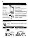
BURNER
ASSEMBLY
ORIFICE
LOCATION
FIGURE 64
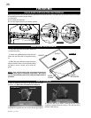
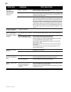
FIGURE 66
ADJUSTMENTS
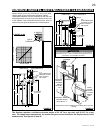
PILOT INJECTOR AND ORIFICE REPLACEMENT
VENTURI ADJUSTMENT
Remove the 2 screws securing the burner. Natural gas models have air shutters set to 0.031" open (1/32"). Propane models
have air shutters set to 0.063" open (1/16").
After making adjustments replace the burner ensuring that the venturi tube fi ts over the orifi ce and replace the screws.
Closing the air shutter will cause a more yellow fl ame, but can lead to
carboning. The fl ame may not appear yellow immediately; allow 15 to 30
minutes for the fi nal fl ame colour to be established.
Air shutter adjustment must only be done by a qualifi ed gas installer!
This must be carried out by an AUTHORIZED
REPRES ENTATIV E OF WOLF ST EE L LTD. or a QUAL IF IED
GAS INSTALLER in accordance with local codes or in
the absence of local codes with the requirements of the
provincial / state authorities having jurisdiction and in
accordance with the requirements of the CAN1-B149
Installation Code in Canada and the ANSI Z223.1 National
Fuel Gas Code in the United States.
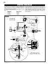
FLAME ADJUSTMENT
Turn counterclockwise
to decrease fl ame
height
Turn clockwise to
increase fl ame height
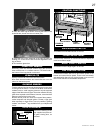
FIGURE 67
For fuel conversion refer to the instructions included with your conversion kit.
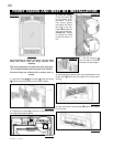
FLAME CHARACTERISTICS
It is important to periodically perform a visual check
of the pilot and burner fl ames. Compare them to the
illustrations provided.
FIGURE 68
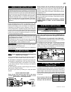
Manual Shut-off Valve
Shown in “OFF”
position.
P
I
L
O
T
O
F
F
O
N
FLAME ADJUSTMENT
KNOB