


17
W415-0612 / C / 01.25.08
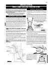
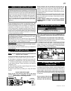
HORIZONTAL INSTALLATION
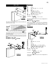
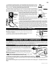
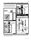
VERTICAL INSTALLATION
INSTALLATION
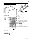
WALL AND CEILING PROTECTION
FIGURE 19
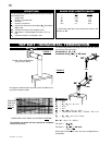
This application occurs when venting through an exterior
wall. Having determined the correct height for the air terminal
location, cut and frame a hole in the exterior wall 9 7/8" wide
by 11 3/8" high to accommodate the fi restop assembly. Dry
fi t the fi restop assembly before proceeding to ensure the
brackets on the rear surface fi t to the inside surface of the
horizontal framing. Firestop spacer and shield do not limit
the thickness of a wall. For wall construction when using less
than 2" x 6" framing, the shield must be cut to suit.
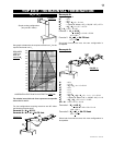
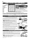
As an alternative to framing, the vent pipe can be enclosed
in the wall using Napoleon
®
vent sleeve VS47KT.
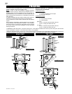
NOTE: THE FIRESTOP ASSEMBLY MUST BE
INSTALLED WITH THE VENT SHIELD TO THE TOP.
The length of the vent shield may be cut shorter for combustible
walls that are less than 8 1/2" thick but the vent shield must
extend the full depth of the combustible wall.
1. Apply a bead of caulking (not supplied) around the corner
edge of the inside surface of the fi restop assembly, fi t the
fi restop assembly to the hole and secure using the 4 screws
(W570-0026) supplied in your manual baggie.
2. Once the vent pipe is installed in its fi nal position, apply
high temperature sealant W573-0002 (not supplied) between
the pipe and the fi restop.
NOTE: DO NOT FILL THE CAVITY BETWEEN THE PIPE
/ LINER AND THE FIRESTOP SLEEVE WITH ANY TYPE
OF MATERIAL.
FIGURES 21a&b
FIRESTOP
UNDERSIDE OF JOIST
9
3
/4”
9
3
/4”
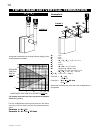
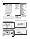
FIGURE 20
For optimum performance, it is recommended that
horizontal runs have a minimum 1" rise per foot when
using Simpson Dura-Vent, Selkirk Direct Temp,
American Metal Amerivent, or Wolf Steel rigid or
fl exible vent components.
For safe and proper operation of the fi replace,
follow the venting instructions exactly.
CAULKING
VENT PIPE
SHIELD
VENT
PIPE
COLLAR
VENT PIPE
SHIELD
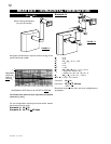
This application occurs when venting through a roof.
Installation kits for various roof pitches are available from
your Napoleon® dealer. See Accessories to order the specifi c
kit required.
1. Determine the air terminal location, cut and frame a 9
3/4" square opening in the ceiling and the roof to provide
the minimum clearance between the vent pipe and any
combustible material. Try to center the vent pipe location
midway between two joists to prevent
having to cut them. Use a plumb bob to
line up the center of the openings.
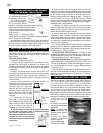
Do not fi ll this space with any
type of material.
A vent pipe shield will prevent any materials such as insulation,
from fi lling up the 1" air space around the pipe. Nail headers
between the joist for extra support.
2. Apply a bead of caulking (not supplied) to the framework
or to the Wolf Steel vent pipe shield plate or equivalent (in the
case of a fi nished ceiling), and secure over the opening in
the ceiling. A fi restop must be placed on the bottom of each
framed opening in a roof or ceiling that the venting system
passes through. Apply a bead of caulking all around and
place a fi restop spacer over the vent shield to restrict cold
air from being drawn into the room or around the fi replace.
Ensure that both spacer and shield maintain the required
clearance to combustibles. Once the vent pipe is installed
in its fi nal position, apply sealant between the pipe and the
fi restop assembly.
3. In the attic, slide the vent
pipe collar down to cover up
the open end of the shield and
tighten. This will prevent any
materials, such as insulation,
from fi lling up the 1" air space
around the pipe.