


MAYCO ST-45HRM CE PUMP — OPERATION & PARTS MANUAL — REV. #0 (02/23/04) — PAGE 55
ST-45HRM CE CONCRETE PUMP— MAINTENANCE (PUMP)
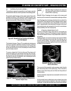
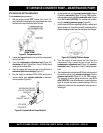
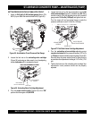
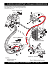
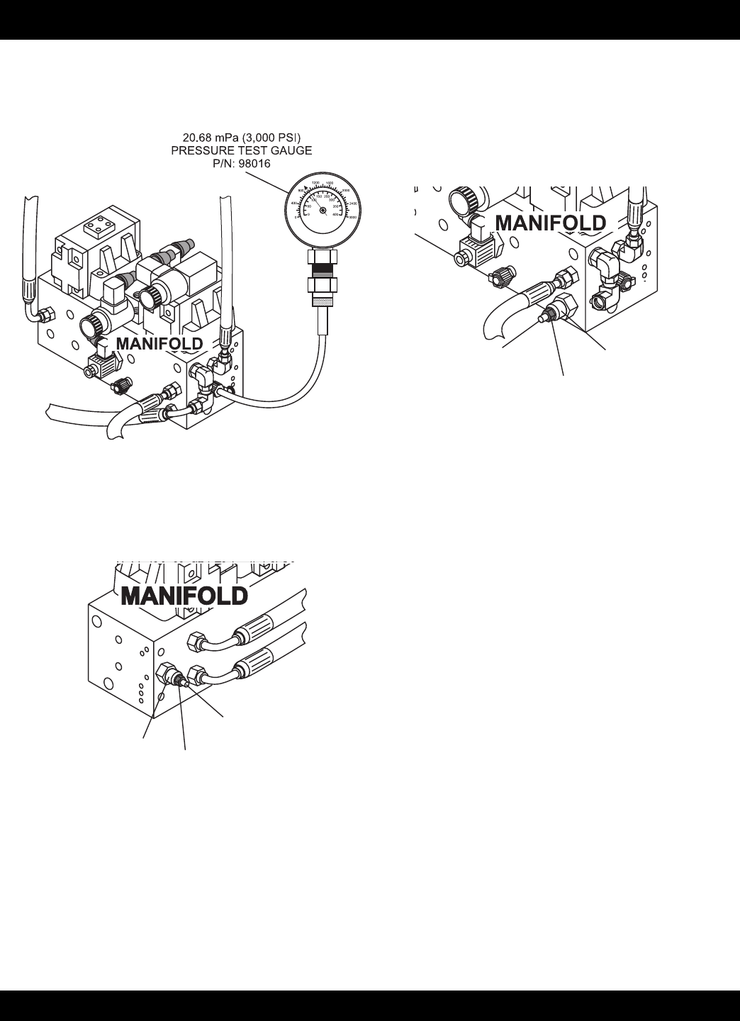
Figure 55. Accumulator Circuit Pressure Test Gauge
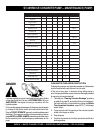
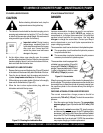
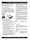
UNLOADING
VALVE CARTRIDGE
LOCK NUT
ADJUSTMENT
SCREW
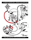
Figure 56. Unloading Valve Cartridge Adjustment
SETTING PRESSURE IN THE ACCUMULATOR CIRCUIT
1. Attach a
20.68 mPa (3,000 psi)test gauge
(Mayco P/N
98016) to port
G2
of the main manifold block (Figure 55).
2. Loosen the lock nut on the
unloading valve cartridge
(Figure 56) and using an allen wrench, turn the adjusting
screw
clockwise
until it is completely closed.
3. Turn the
pump control switch
(Figure 22) to the “ON”
position and run engine at 2,550 RPM.
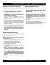
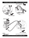
4. Loosen the lock nut for the the accumulator circuit
pilot
relief valve cartridge
(Figure 57), located at port
G4
. Using
an allen wrench, turn the adjusting screw until pressure
gauge reads 13.44 mPa (1,950 psi) and tighten lock nut.
Turn the engine off and on several times to make the
pressure continues to read 13.44 mPa (1,950 psi).
5. Turn the
unloading valve cartridge
adjusting screw
counter-clockwise
until the pressure reaches 12.07 mPa
(1,750 psi)
on the accumulator pressure gauge (Figure 29).
Start and stop the pump several times to make sure the
accumulator circuit pressure is holding at 12.07 mPa (1,750
psi).
6. Tighten the lock nut on the unloading valve cartridge. Your
accumulator circuit pressure should now be properly
adjusted.
Figure 57. Pilot Relief Valve Cartridge Adjustment
PILOT RELIEF
VALVE CARTRIDGE
LOCK NUT
ADJUSTMENT
SCREW