


MAYCO ST-45HRM CE PUMP — OPERATION & PARTS MANUAL — REV. #0 (02/23/04) — PAGE 21
ST-45HRM CE CONCRETE PUMP— PUMP COMPONENTS
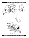
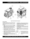
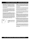
Figure 7 illustrates the location of the major components
for the ST-45 Structural Concrete Pump. The function of
each component is described below:
1. Tow Hitch Coupler – See the Towing Information
section in this manual.
2. Documentation Box – Contains engine and pump
operation, parts and maintenance information.
3. Hydraulic Oil Tank/Cap– Remove cap to add hydraulic
fluid. Fill with Shell Oil Tellus 68, Mobil Oil DFE26 or
equavalent if hydraulic oil level is low.
4. Fuel Tank/Cap – Fill with #2 diesel fuel. Fuel tank (cell)
holds approximately 88 liters (20 gallons). DO NOT top off
fuel. Wipe up any spilled fuel immediately
5. Battery – This unit uses a +12 VDC type battery.
ALWAYS
use gloves and eye protection when handling the battery.
6. Heat Exchanger – Reduces temperature of the hydraulic
oil. The exchanger draws oil from the hydraulic tank through
a filter and into the heat exchanger before allowing it to
flow into the hydraulic system.
7. Lubrication Box – This box is empty when shipped
from the factory. Please fill with 7 gallons ( 26.5 liters) of
SAE motor oil for first time use. Also check the dual
clean-out point on bottom of lubrication box for a secure
tight fit.
8. Tires — Tire inflation pressure is the most important factor
in tire life. Pressure should be checked before operation.
DO NOT bleed air from tires when they are hot. Check
inflation pressure weekly during use to insure the maximum
tire life and tread wear.
9. Shuttle Cylinder – Under pressure, the shuttle cylinder
shears concrete passing from the concrete cylinder to
the delivery line durring the cycle phase. The
Accumulator provides the pressure needed to ensure
enough force is provided during cycle.
10. Pump End Jack Stand – Use this jack stand to level
and support the rear end of the pump. NEVER deploy
on un-level ground and always check for firmness of
ground.
11. Hopper/Hood – Lift hood to fill. Concrete from a Redi-Mix
truck is poured into this hopper. The hopper can hold 283
liters (10 cu. ft) of concrete with optional forward/reverse
mixer. NEVER put hands or any other parts of you body into
the hopper.
12. Remixer Motor – Drives the remixer paddles inside
the hopper. The motor direction is controled by the
remixer control lever.
13. Lubrication Panel – This console allows for the remote
lubrication of components on the pump.
14. Rear Running Lights – ALWAYS check and make sure
both the right and left running lights are functioning correctly
before towing the pump.
15. Accumulator – Stores hydraulic oil under pressure and
releases it to the shuttle cylinder and provides the
required pressure to activate the hydraulic system.
16. Remixer Control Lever – Controls the forward/reverse
motion of the hopper remixer paddles.
17. Manifold – Aluminum block that controls the flow of
hydraulic pressure to the various hydraulic motors and other
components required to control the pump.
18. Hydraulic Pump – This unit incorporates an axial variable
displacement hydraulic piston pump.
19. Throttle Control Knob – This is a variable speed type
control. Turning the throttle lock (CCW) left unlocks the
throttle allowing the throttle control cable to be pulled out to
the desired position. Once the desired throttle position
(speed) has been achieved, turning the throttle lock to the
(CW) right locks it in place. Use the fine tune adjustment
knob to fine tune the engine rpm's.
To place the engine in idle, press the top button inward all
the way..
20. Stroke Volume Control Dial – Turns CW/CCW to increase
or decrease the number of strokes per minute of the pump.
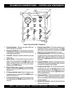
21. Control Box – Contains the mechanical and electrical
components required to run the pump. See next page for
control box description.
22. Tow End Jack Stand – Use this jack stand to level and
support the tow end of the pump.
23. Pumping Pressure Gauge – Used to monitor pressure in
the concrete cylinders and shuttle tube.
24. Accumulator Pressure Gauge– Used to monitor
accumulator pressure. Pressure should read at least 12.1
mPa (1,750 psi) for correct pump operation.
25. Hydraulic Oil Sight Glass – Use to determine the
amount of hydraulic oil remaining in tank. The sight
glass also contains a temperature gauge for monitoring
the temperature of the hydraulic oil.
26. Hopper Discharge Sleeve – Connect hoses or steel
pipes to the discharge sleeve for pouring concrete.
27. Emergency Stop Button – Press emergency stop button
to stop pump in an emergency. Turn knob counter clockwise
to disengage the stop button.