


MAYCO ST-45HRM CE PUMP — OPERATION & PARTS MANUAL — REV. #0 (02/23/04) — PAGE 41
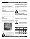
3.0 BRAKING SYSTEM
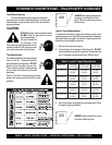
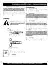
3.1 WHEEL JACKING
On level ground, with the hand brake lever in the off position and
overrun coupling draw tube shaft fully extended forwards, secure
one wheel with wheel chocks. Position your jacking device behind
the opposite wheel, as near to a main longitudinal chassis
member as possible. Lift the wheel clear of the ground and secure
with suitable axle stands.
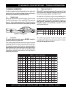
3.2 BRAKING SYSTEM ADJUSTMENT
Where the transmission rod and brake cables are already
connected, take the tension out of the system by winding back
the nuts on the rod behind the compensator.
It is now possible to begin the setup procedure:
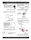
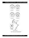
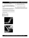
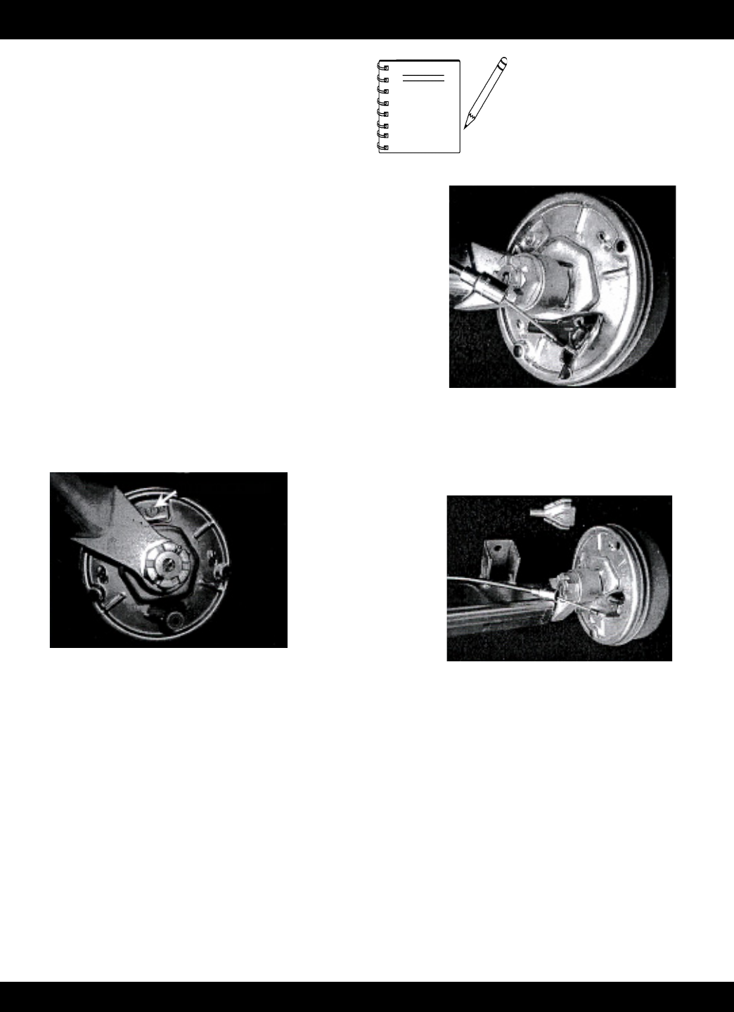
3.3 WHEEL BRAKES
These can be adjusted by means of a 17mm, 19mm, or 24mm
AF Spanner (dependant on brake type) on the adjuster bolt head
at the rear of the brake back plate. Reference Figures 40A, B
and C.
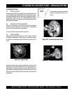
Adjuster Bolt
Rotate each wheel only in the forward direction of travel, whilst
tightening the bolt until the wheel locks. Then, gradually back off
the adjuster nut until the wheel can rotate forwards with just a
slight resistance/audible brushing of the brake drum on the brake
linings (this is best adjusted with the wheel and tyre fitted to the
brake drum).
Figure 40A. Adjuster Bolt
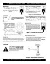
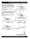
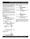
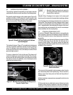
Figure 40B. Connecting Sheated Cable
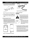
Figure 40C. Connecting Sheated Cable
NOTE
If not already connected, connect the
Bowden (sheathed) cables to the
brakes.
ST-45HRM CE CONCRETE PUMP— BRAKING SYSTEM