


PAGE 32 — MAYCO ST-45HRM CE PUMP — OPERATION & PARTS MANUAL — REV. #0 (02/23/04)
EMERGENCY STOP SWITCH
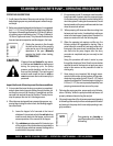
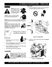
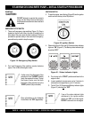
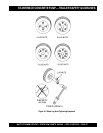
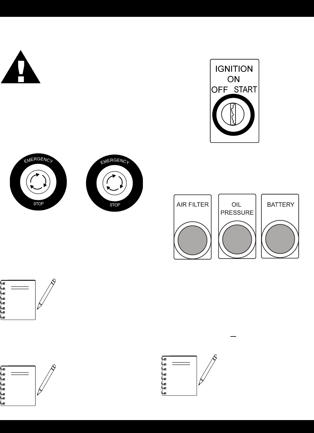
1. There are 2 emergency stop switches (Figure 19). One is
located on the the control box, the other is located on the
other side of the pump near the heat exchanger. Both are
provided for operator safety. In the event of an emergency,
press either stop switch to stop the engine.
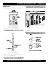
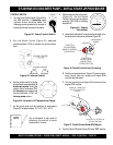
IGNITION SWITCH
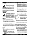
3. To start the engine, insert the key (Figure 20) into the ignition
switch and turn the key to the ON position.
Figure 19. Emergency Stop Switch
Figure 20. Ignition Switch
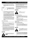
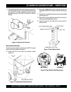
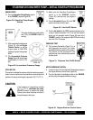
Figure 21. Status Indicator Lights
ST-45HRM CE CONCRETE PUMP— INITIAL START-UP PROCEDURE
4. Observe that the Air Filter and Oil Pressure status indicator
lights are “ON” (Figure 21). The Battery status indicator light
should be “OFF.”
DO NOT attempt to operate this concrete
pump until the Safety, General Information
and Inspection sections have been read and
understood.
STARTING
CAUTION :
If either one of the Emergency Stop
switches is in the “CLOSED” position
(stop), the engine will not start. To start
the engine, make sure that both
Emergency Stop switches are in the
“OPEN” position (fully extended).
Place all switches on the Hydraulic
Control Box in the ”OFF” (up position).
NOTE
NOTE
2. Turn both Emergency Stop switches counter-clockwise
(open). This will allow the engine to start.
A. Turn the key to the “START“ position and listen for the
engine to start.
B. In warm weather let engine warm-up for 5 minutes. In
cold weather let engine warm-up for 10 minutes.
C. The Air Filter, Oil Pressure and Battery indicator lights
(Figure 21) should
all be “OFF”.
If any of the status indicator lights
referenced in the ignition section
(step 4) are “ON”, turn off the engine.
DO NOT continue to run the engine.
NOTE