


PAGE 42 — MAYCO ST-45HRM CE PUMP — OPERATION & PARTS MANUAL — REV. #0 (02/23/04)
3.4 COUPLING AND TRANSMISSION SYSTEM
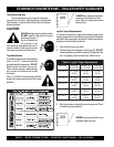
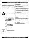
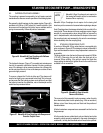
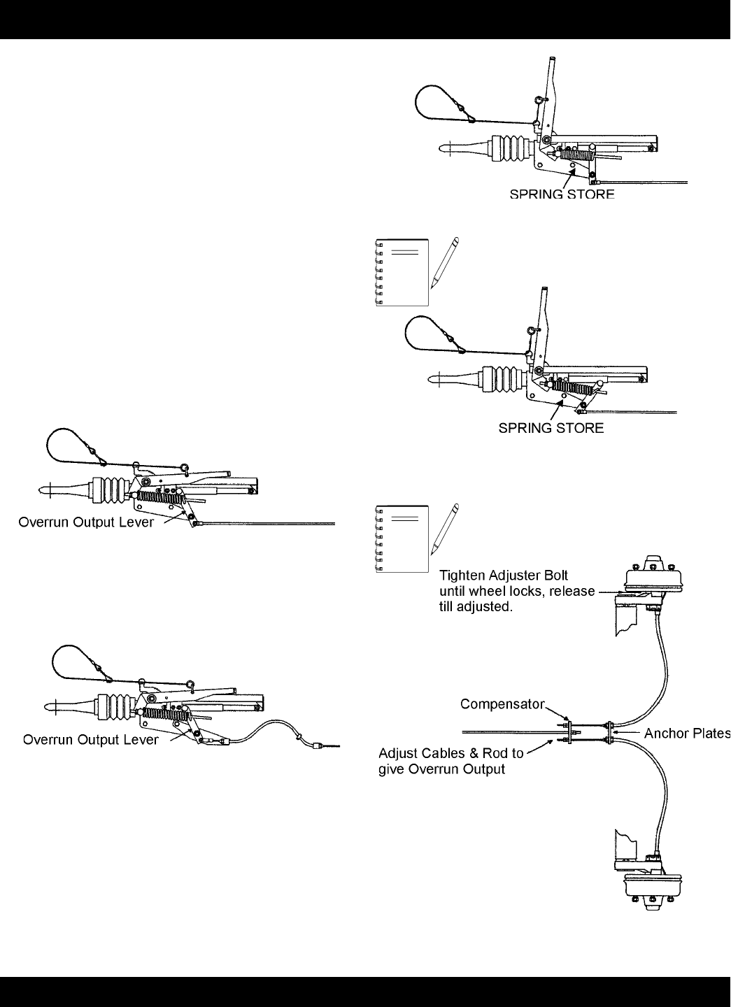
Attach the opposite end of the outer cable to the anchor plate
(Figure 41E) on the axle or draw bar, using the nut provided.
Connect the inner cables to the compensator, locking the 2 plain
nuts together in front of the compensator for each cable. If not
already connected, attach the rear end of the brake rod to the
compensator center hole.
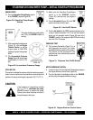
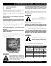
COUPLINGS WITH HANDBRAKE MOUNTED ON COUPLING
BODY (FIGURES 41A-41E)
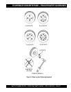
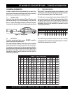
Use the plain nuts behind the compensator to adjust, until the
overrun output lever can be pulled rearwards by firm hand
pressure (not loose) a maximum of 14mm (16mm for adjustable
height models.) For knott couplings, there should not be any
movement
Maintain the compensator at 90° to the draw bar for even
distribution of force into each cable. Ensure the cables are not
“kinked” or damaged.
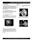
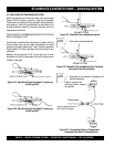
Figure 41A. Meredith & Eyre Fixed Height Coupling up
to 2500 kg GVM
Figure 41B. Meredith & Eyre Fixed Height Coupling up
to 2000 kg GVM
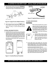
Figure 41C. Meredith & Eyre Handbrake Applied
NOTE
Spring Store now compressed
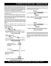
Figure 41D. Meredith & Eyre Handbrake After Automatic
Activation In the Reverse Mode
Spring Store now extended, handbrake will
feel less tensioned.
Figure 41E. Connecting Cables to Compensator
Handbrake Mounted On Coupling Body
NOTE
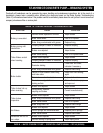
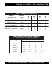
ST-45HRM CE CONCRETE PUMP — BRAKING SYSTEM